Apparatus and method for controlled delivery of a gas

A technology of conveying equipment and equipment, which is applied in sanitary equipment for toilets, chemical instruments and methods, life-saving equipment, etc., and can solve problems such as difficult to control the time of efficient gas generation, occupying space, increasing costs, etc.

Inactive Publication Date: 2005-06-15
SELECTIVE MICRO TECH
View PDF4 Cites 3 Cited by
  • Summary
  • Abstract
  • Description
  • Claims
  • Application Information

AI Technical Summary

Problems solved by technology

These devices take up a lot of space and imply considerable added expense
Moreover, even when prior art devices do not require a separate gas generating component, such as those shown in European Patent Publication No. 0571228 for the generation of sulfur dioxide, such devices are still undesirable because then already Demonstrated difficulty without unsuccessful control of the amount of gas produced, the efficiency with which it is produced, and the timing of gas production

Method used


Image

  • Apparatus and method for controlled delivery of a gas
  • Apparatus and method for controlled delivery of a gas
  • Apparatus and method for controlled delivery of a gas

Examples


Embodiment 1

[0291] Example 1: Device according to the invention

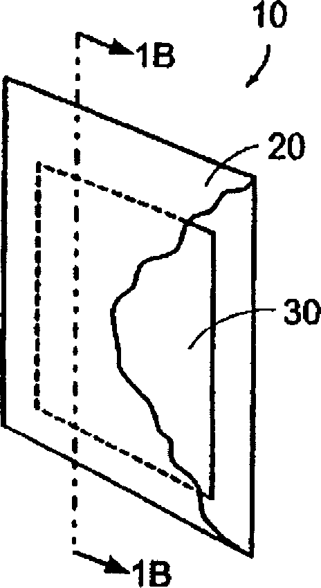
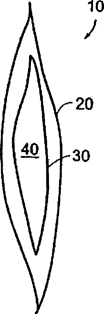
[0292]A film pouch was constructed by pulse sealing the perimeter of two 3 cm x 3 cm hydrophilic polypropylene film sheets sold by Millipore (Bedford, MA) under the trade name MPLC with a pore diameter of 0.65 microns. The sheets were pulse sealed using a 16″ TISH400 pulse sealer available from TEW Electric Heating Equipment Corporation (Taiwan). The bag contained 50 mg sodium chlorite and 200 mg citric acid. The bag was then placed through a 4 cm x 6cm perforated film in an envelope formed by pulse sealing the periphery. The perforated film used was SM700Cryovac® perforated film produced by Sealed Air Corporation (Duncan, SC). The assembly was then placed in a water-filled 1 Liter plastic bags for 15 minutes. The concentration of chlorine dioxide in the water was measured to be approximately 6 mg / L by a Beckman DU-520 UV-Vis spectrophotometer set at a wavelength of 360λ.

Embodiment 3

[0295] Example 3: Device without envelope

[0296] A device was constructed as described in Example 1, but without the envelope. The assembly was then placed in a 1 liter plastic bag with water for 15 minutes. The chlorine dioxide concentration in the water was measured to be approximately 5.5 mg / L using a Beckman DU-520 UV-Vis spectrophotometer set at a wavelength of 360λ. exist Figure 10 Such a device and its exemplary use are shown in .

example 4

[0297] Example 4: Device with two bags.

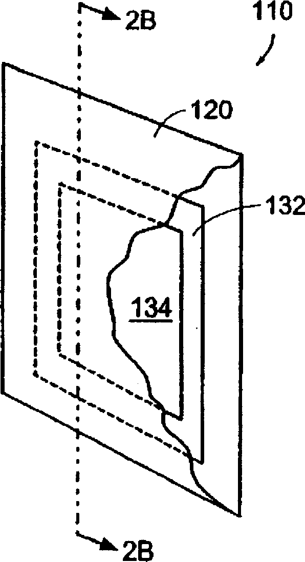
[0298] Two pouches were constructed by pulse sealing the perimeter of four 3 cm x 3 cm hydrophilic polypropylene film sheets sold under the trade name MPLC by Millipore (Bedford, MA) with a pore diameter of 0.65 microns. The first bag was filled with 400 mg sodium chlorite and the second bag was filled with 1200 mg citric acid. The two bags were then enclosed in an envelope formed by pulse sealing the perimeter of a 4 cm x 6 cm SM700 film from Sealed Air Corporation having 330 holes per square inch of 0.4 mm diameter with a 6.4% perforated area And has 700g / m 2 / 24-hour water vapor transmission rate. The device was then placed in a 1 liter plastic bag with water and allowed to stand for 180 minutes. The chlorine dioxide concentration in the water was measured to be approximately 100 mg / L using a Beckman DU-520 UV-Vis spectrophotometer set at a wavelength of 360λ.


PUM

PropertyMeasurementUnit
diameteraaaaaaaaaa
thicknessaaaaaaaaaa
diameteraaaaaaaaaa

Abstract

The present invention discloses devices for transporting gases such as carbon dioxide and / or chlorine dioxide, and methods of use and manufacture thereof. The device includes a bag (30) constructed in part of a hydrophobic material. The bag (30) contains one or more reactants (40) which, in the presence of an initiator such as water, generate a gas. The device may also include a barrier layer (550) and / or a rigid frame. In another embodiment, the device is combined with a container (1845), which can be used to deliver gas to the container and optionally a pipeline. In another embodiment, the apparatus is installed in a fluid distribution system that includes a distribution device such as a humidifier.

Description

[0001] related application [0002] This application claims U.S. Provisional Patent Application No. 10 / 225769, filed August 22, 2002, 60 / 190028, filed March 17, 2000, filed February 2000, under 35 U.S.C § 119(e) 60 / 183368 filed on the 18th, 60 / 259896 filed on January 4, 2001, and 60 / 341429 filed on December 17, 2001 and claiming co-pending 2000 under 35 U.S.C § 120 US Patent Application No. 09 / 660117, filed September 12, and the benefit of 09 / 785,634, filed February 16, 2001, each of which is incorporated herein by reference in its entirety. technical field [0003] The present invention relates generally to apparatus and methods for delivering gas, and more particularly to apparatus and methods for controlling the amount, velocity and timing of gas delivery. Background technique [0004] Use of gases to inhibit, control, kill or prevent microbial contamination (e.g., bacteria, fungi, viruses, mold spores, algae and protozoa); inhibit, prevent or control biochemical breakdo...

Claims


Application Information

Patent Timeline
Patent Type & Authority Applications(China)
IPC IPC(8): A23L2/42A23L3/3409A61L2/20A61L9/01A61L9/015B01J7/00C01B11/02C01B32/50C02F1/00C02F1/68C02F1/76G06Q10/10H04L12/18
CPCA61L2/20A61L9/015C01B11/022C01B11/024C02F1/00C02F1/68C02F1/76C02F1/763C02F2303/04G06Q10/10Y10S422/902
Inventor R·A·哈米尔顿J·J·瓦纳
Owner SELECTIVE MICRO TECH
Why Eureka
Try Eureka