Continuous reactive power support for wind turbine generators

A technology of generators and wind turbines, which is applied in the control of wind turbines, wind power generation, reactive power adjustment/elimination/compensation, etc., and can solve problems such as voltage reduction

Active Publication Date: 2005-06-22
GENERAL ELECTRIC CO
View PDF0 Cites 37 Cited by
  • Summary
  • Abstract
  • Description
  • Claims
  • Application Information

AI Technical Summary

Problems solved by technology

Conversely, the reduced reactive power component (i.e., inductive VAR) will cause the voltage to drop

Method used


Image

  • Continuous reactive power support for wind turbine generators
  • Continuous reactive power support for wind turbine generators
  • Continuous reactive power support for wind turbine generators

Examples


Embodiment Construction

[0022] In the following description, for purposes of explanation, numerous specific details are given in order to provide a thorough understanding of the present invention. It will be apparent, however, to one skilled in the art that the invention can be practiced without these specific details. In other embodiments, structures and devices are shown in block diagram form in order to avoid obscuring the invention.

[0023] The techniques described here provide voltage to utilize the total capacity of the wind turbine generator system (ie, wind farm), thereby providing dynamic VAR (Var Support). The VAR support provided by individual wind turbine generators in the system can be changed dynamically to suit the usage parameters.

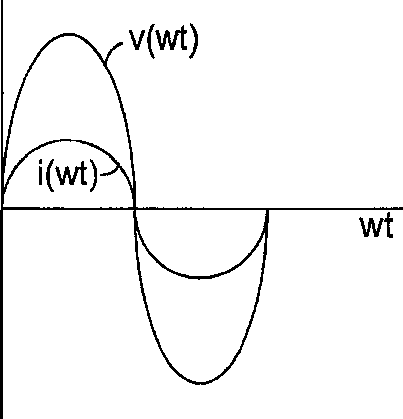
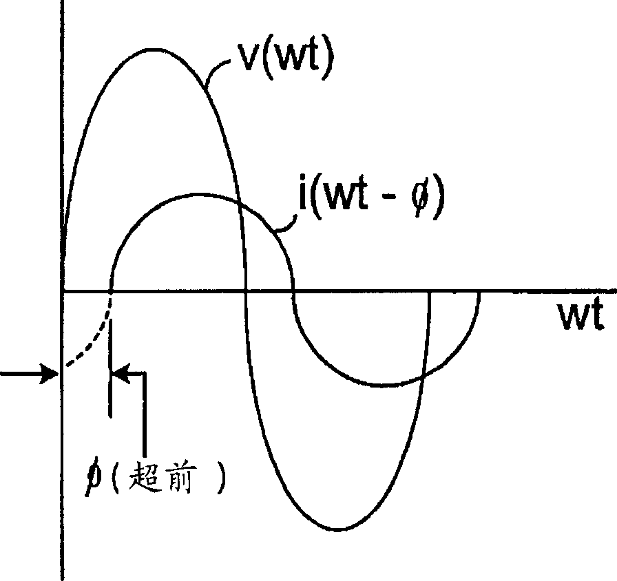
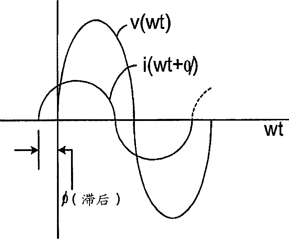
[0024] Wind turbine generators can provide VAR support based on real power production and power factor. Such VAR support can be expressed, for example, by the equation:

[0025] VAR=Watt*tan(θ)

[0026] where θ is the power factor angle. Power facto...


PUM


Abstract

Active and reactive power control for wind turbine generator systems. The techniques described here provide voltage to utilize the total capacity of the wind turbine generator system (400), thereby providing dynamic VAR (Var Support). The VAR support provided by individual wind turbine generators (410, 412) in the system can be changed dynamically to suit usage parameters.

Description

technical field [0001] The present invention relates to the generation and distribution of electrical power. More specifically, the present invention relates to compensation of electric power supply for reactive loads. Background technique [0002] The transmission and distribution grid sends electrical energy from generators to end users. Voltage management on a transmission and distribution system is an important factor in the operation and design of that system. In a typical system, reactive power flow has a large effect on voltage. Reactive power flow can be affected by generation sources, changes in transmission and distribution systems, addition of bypass reactive elements, and loads. Additionally, excessive reactive power flow can raise voltage and place undue stress on transmission lines, transformers, and other electronic components. [0003] refer to figure 1 , 2 and 3, electrical power has at least two properties related to power distribution: voltage and cu...

Claims


Application Information

Patent Timeline
Patent Type & Authority Applications(China)
IPC IPC(8): F03D7/02H02J3/18H02P9/00
CPCF03D7/02F03D7/0272F05B2260/96F05B2270/337H02J3/1842H02P9/007H02J3/16H02P2101/15F03D9/255F03D9/257H02J2300/28H02J3/381Y02E10/72Y02E10/76Y02E40/20Y02E40/30
Inventor T·A·维尔金斯N·M·埃尔卡霍蒂R·A·瓦林J·P·莱昂斯R·W·德尔梅里科S·波斯N·W·米勒
Owner GENERAL ELECTRIC CO
Why Eureka
Try Eureka