

Refrigerating machine having refrigerant/water heat exchanger
A technology for water heat exchangers and heat exchangers, which is applied to compressors with multiple evaporators, refrigerators, refrigeration components, etc. Condensation, heat exchange efficiency improvement, and cost reduction effects
- Summary
- Abstract
- Description
- Claims
- Application Information
AI Technical Summary
Problems solved by technology
Method used
Image

Examples
Embodiment Construction
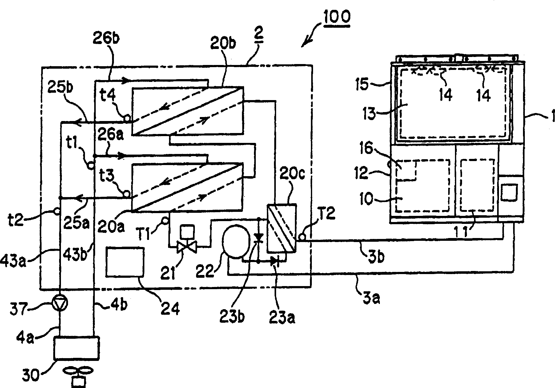
[0048] Hereinafter, embodiments of the present invention will be described in detail with reference to the drawings. figure 1 It is a diagram of a system structure including a refrigerant circuit of a refrigerating apparatus applicable to the present invention. The refrigeration device 100 is configured by connecting the heat source unit 1 and the heat exchange unit 2 with refrigerant pipes 3 a and 3 b.
[0049] In the heat source unit 1, a gas engine 10 or a compressor 11 operated by the gas engine 10 and a heat exchange unit 2 for controlling the gas engine 10 or the like or the heat exchange unit 2 described later are provided on a base frame not shown. The machine room 12 such as the heat source side control device 16 for communication with the exchange side control device 24, and the above machine room 12 is provided with an outdoor heat exchanger 13 and a blower fan 14 for blowing air to the outdoor heat exchanger 13. Etc. heat exhaust chamber 15.
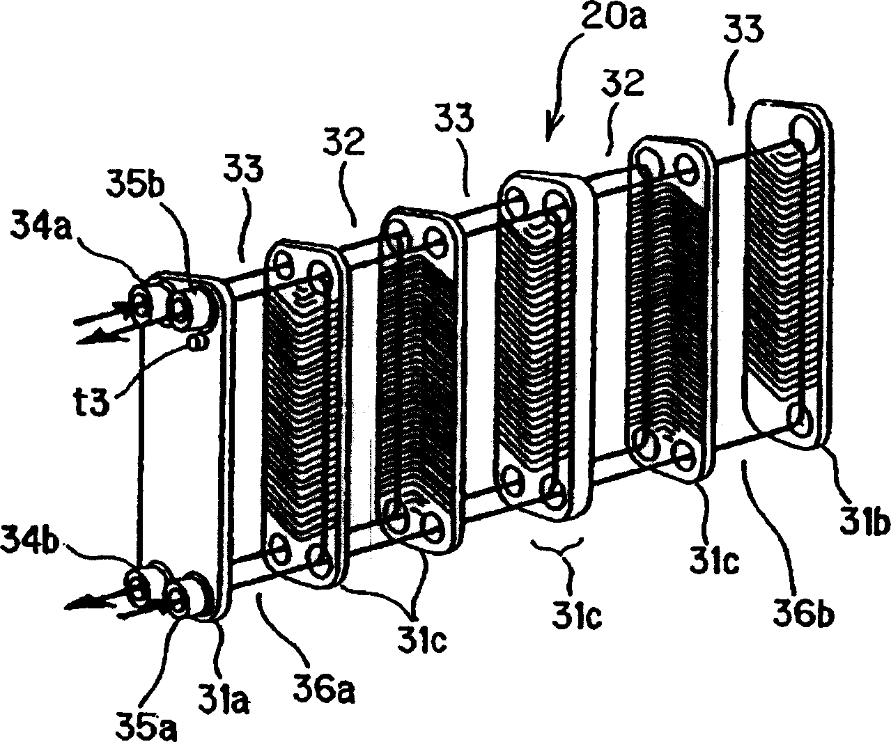
[0050] The heat exc...
PUM
 Abstract
Description
Claims
Application Information