
Window brightness enhancement for LC display

A liquid crystal display and signal display technology, applied in static indicators, cathode ray tube indicators, instruments, etc., can solve problems such as difficult to achieve fast response time of lamps

Inactive Publication Date: 2005-07-27
KONINK PHILIPS ELECTRONICS NV
View PDF1 Cites 2 Cited by
  • Summary
  • Abstract
  • Description
  • Claims
  • Application Information

AI Technical Summary

Problems solved by technology

[0006] Due to the current control structure and the intrinsic behavior of the lamp, it is difficult to achieve a fast response time of the lamp when the amount of light produced needs to be changed

Method used


Image

  • Window brightness enhancement for LC display
  • Window brightness enhancement for LC display
  • Window brightness enhancement for LC display

Examples


Embodiment Construction

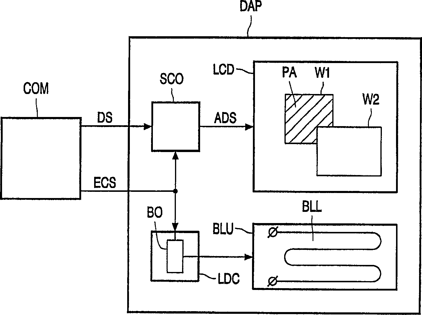
[0024] figure 1 It represents a system of a computer and a display device according to the present invention. This embodiment relates to the case where the lamp must be enlarged due to its slower behavior than the LCD unit. The computer COM provides a display signal DS, which will be displayed on a display device DAP with a liquid crystal display LCD. The computer COM also generates an enhanced control signal ECS, which indicates that the brightness of the predetermined area PA on the liquid crystal display LCD needs to be increased. The enhanced control signal can be embedded in the display signal DS and decoded by the signal controller SCO. The predetermined area PA is, for example, a window W1 generated by an operating system or an application program as shown in the figure. This window is partially covered by window W2.

[0025] The display device DAP also includes a backlight unit BLU with a backlight BLL, which is a liquid crystal display LCD lighting. The lamp driver circ...


PUM


Abstract

In a LCD monitor, a predetermined part (PA) of the displayed information is highlighted by causing the backlighting (BLU) to produce more light. The area outside the predetermined area (PA) is kept at a substantially constant brightness by adjusting the video data driving the panel (LCD). A booster (BO) is added to control the lamp (BLL) such that the amount of light produced by the backlighting (BLU) increases in a controlled and predictable way so the user does not notice a transition in terms of brightness in the area outside the predetermined area (PA).

Description

Technical field [0001] The present invention relates to a system including a display device and a computer, wherein the display device has a liquid crystal display for displaying a display signal, and the computer is used for generating a display signal and an enhancement control signal for indicating the enhancement required for a predetermined area on the liquid crystal display . The invention also relates to a display suitable for such a system. Background technique [0002] From the Philips computer monitors on the market, the features are highlighted (lightframe TM ) Is well known. This feature allows the user to select the area on the screen of the display device where the brightness should be increased. This is particularly advantageous if natural information is displayed on this area. Natural information includes photos and movies that generally have a lower resolution than synthetic information such as text. By increasing the brightness, the perceived quality of this low...

Claims


Application Information

Patent Timeline
Patent Type & Authority Applications(China)
IPC IPC(8): G02F1/133G09G3/20G09G3/34G09G3/36G09G5/10G09G5/14H04N5/57
CPCG09G5/10G09G3/3611G09G2320/0653G09G5/14G09G2320/0686G09G3/3406G09G2320/0646
Inventor G·帕斯奎里尼C·卡萨勒
Owner KONINK PHILIPS ELECTRONICS NV
Features
  • Generate Ideas
  • Intellectual Property
  • Life Sciences
  • Materials
  • Tech Scout
  • Unparalleled Data Quality
  • Higher Quality Content
  • 60% Fewer Hallucinations
Learn More