Roller changer for multiple roller rolling mill

A technology of roll changing device and rolling mill, applied in the direction of metal rolling stand, metal rolling mill stand, metal rolling, etc. Change the roller, provide the effect of working efficiency

Inactive Publication Date: 2005-08-03
郑红专 +1
View PDF0 Cites 10 Cited by
  • Summary
  • Abstract
  • Description
  • Claims
  • Application Information

AI Technical Summary

Problems solved by technology

The traditional drive roller replacement operation is generally manual, using a simple support frame to support and fix the matching parts that the drive roller is connected to, and then remove the original roller and replace it with a new roller. This traditional drive roller replacement operation is very efficient. Low
[0003] In a

Method used


Image

  • Roller changer for multiple roller rolling mill
  • Roller changer for multiple roller rolling mill
  • Roller changer for multiple roller rolling mill

Examples


Embodiment Construction

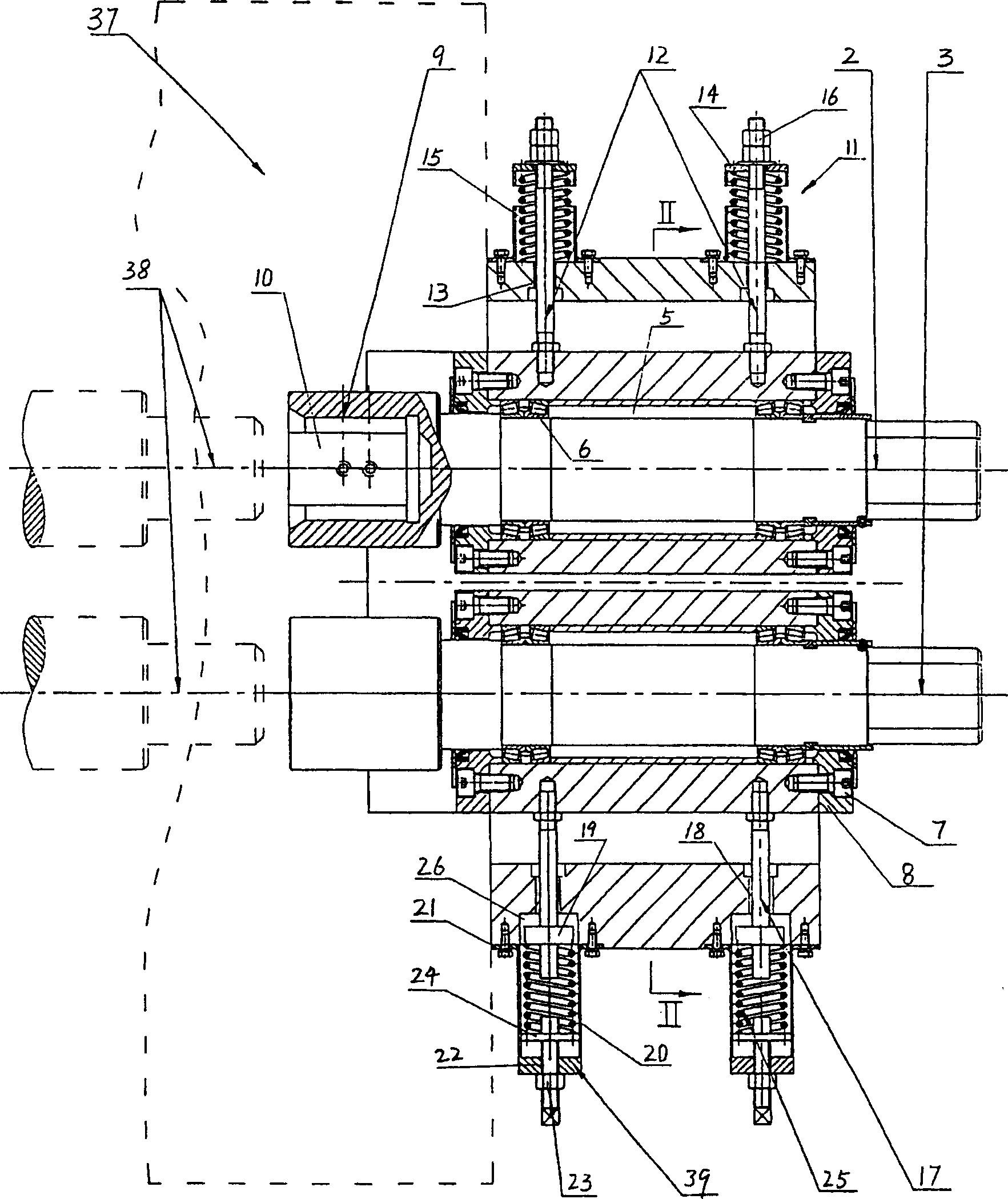
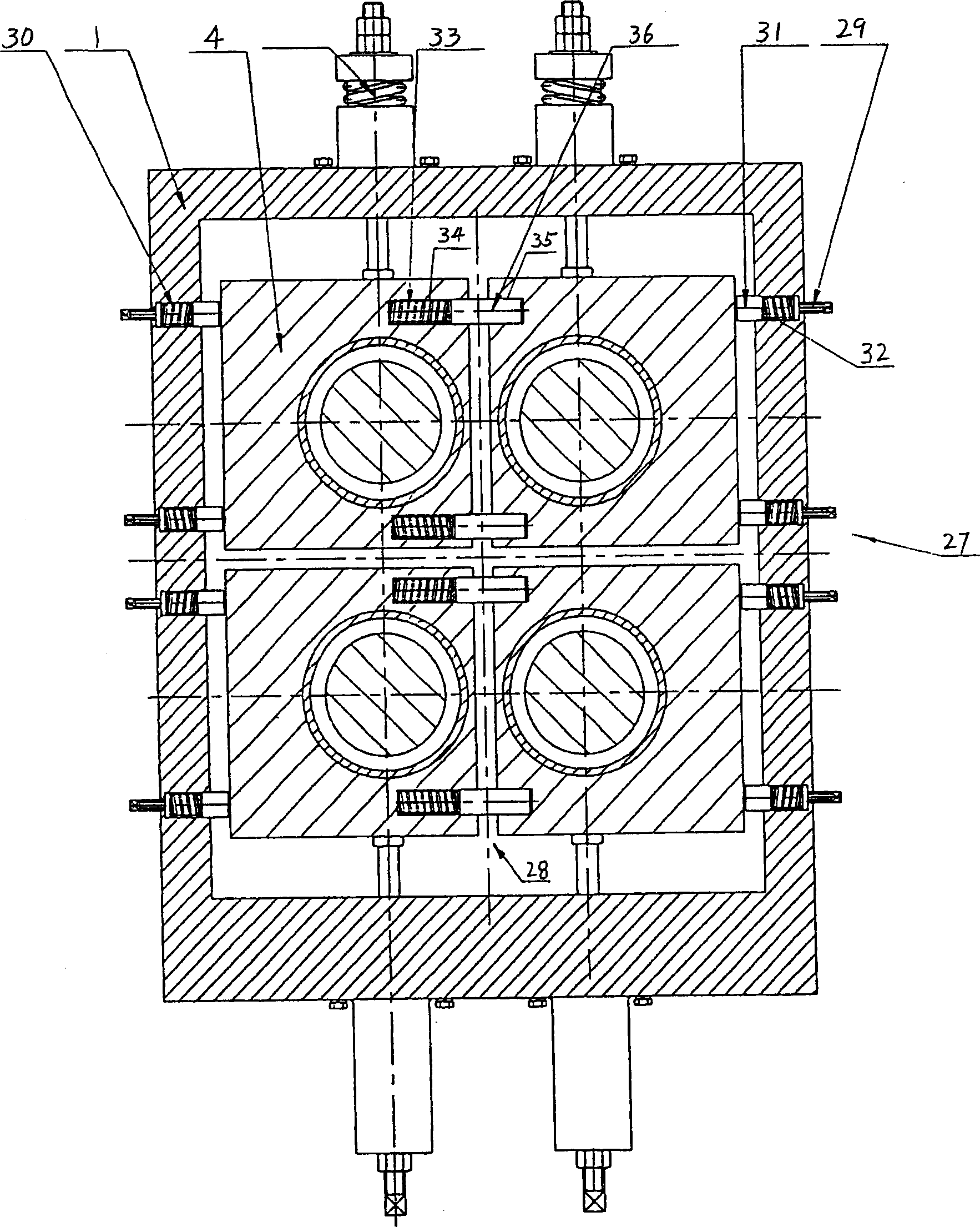
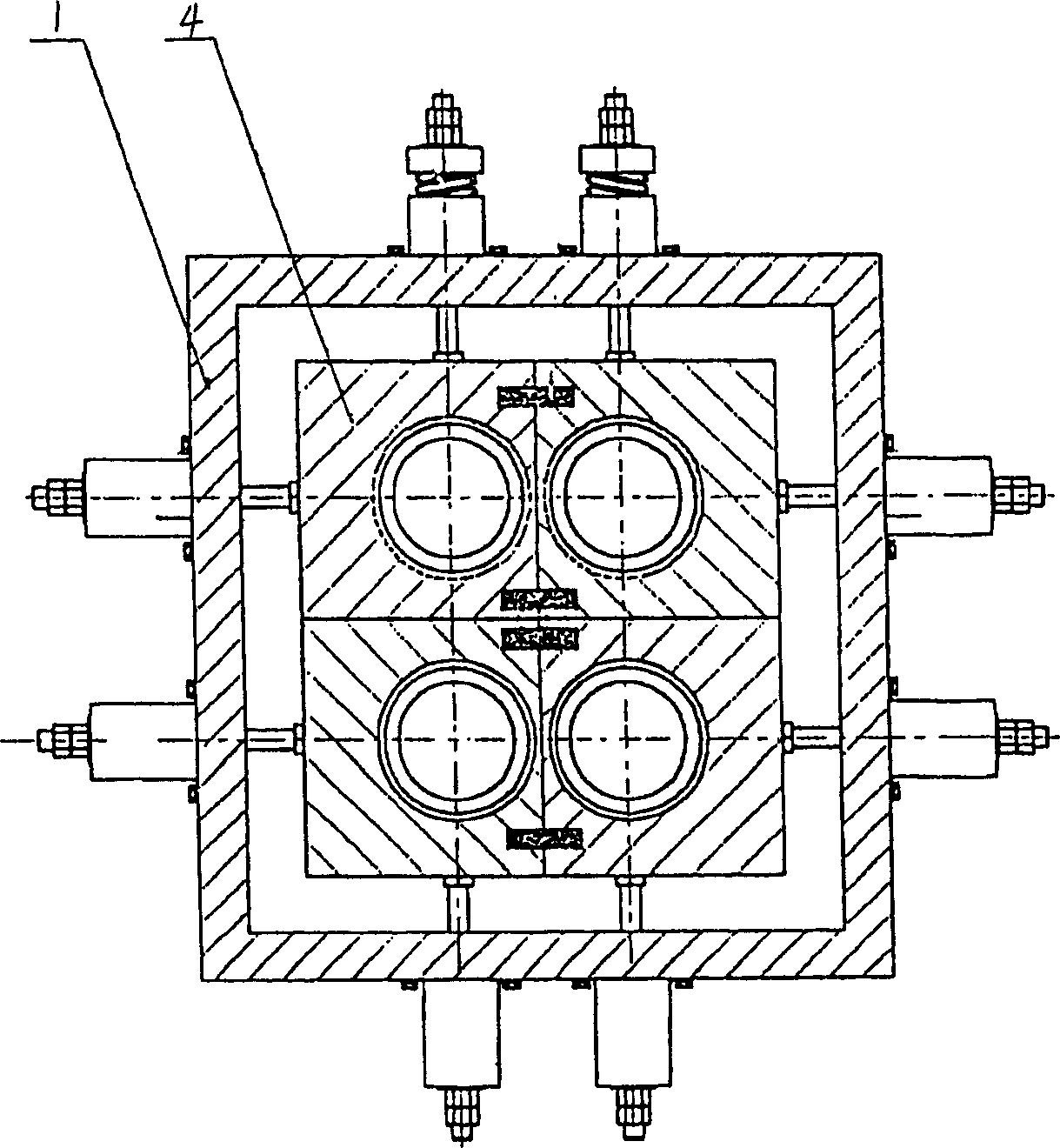
[0023] Below, a preferred embodiment of the roll changing device for a multi-roll rolling mill according to the present invention will be described in detail with reference to the accompanying drawings.

[0024] Such as figure 1 and 2 As shown, the roll changing device for a multi-roll rolling mill according to a preferred embodiment of the present invention includes a frame 1, in which horizontally extending upper and lower connecting shafts 2, 3 and connecting shafts for supporting the corresponding connecting shafts are arranged. Seat 4. In the illustrated embodiment, a total of four connecting shafts 2, 3 are arranged, and the four connecting shafts are arranged in two layers, and each layer includes two connecting shafts arranged side by side. Correspondingly, the illustrated multi-roll rolling mill roll changing device includes four connecting shaft seats 4 arranged in two layers. In the figure, reference numeral 37 denotes a rolling mill archway, and reference numera...


PUM


Abstract

The roller changer for multiple roller rolling mill includes frame, two-layer connecting shaft seats, rotary connecting shafts supported with the connecting shaft seat, and sleeves in one end of the connecting shafts. Under the support of the frame, the connecting shaft seats and thus the connecting shafts may be shifted vertically and/or horizontally, while the sleeves are relatively fixed. The present invention is favorable to the centering of driving rollers and the automatic centering of the sleeves to realize fast roller change in high efficiency.

Description

technical field [0001] The invention relates to a rolling mill auxiliary device, in particular to a roll changing device for a multi-roll rolling mill. Background technique [0002] Rolling mills are commonly used mechanical equipment in the industrial field, and the drive rollers of the rolling mill need to be replaced after a period of use. The traditional drive roller replacement operation is generally to use a simple support frame to support and fix the matching parts that the drive roller is connected to, and then remove the original roller and replace it with a new roller. This traditional drive roller replacement operation is very efficient. Low. [0003] In addition, the inner hole of the traditional simple support frame used is flat, and the end of the drive roller is also flat. Due to the change of the position of the fittings that the drive roller is mated with during the docking, the difficulty of docking is increased, and The labor intensity is high, and the e...

Claims


Application Information

Patent Timeline
IPC IPC(8): B21B31/08B21B31/10B21B31/12
CPCB21B31/08
Inventor 郑红专赵林珍
Owner 郑红专
Why Eureka
Try Eureka