Antenna using variable capacitance element and wireless communication apparatus using the same

一种可变电容、天线的技术,应用在电气元件、电气短天线、天线等方向,能够解决耗时等问题,达到抑制互调失真、减小发热量、抑制波形失真的效果

Inactive Publication Date: 2005-08-03
KYOCERA CORP
View PDF3 Cites 14 Cited by
  • Summary
  • Abstract
  • Description
  • Claims
  • Application Information

AI Technical Summary

Problems solved by technology

[0018] Furthermore, similar to the above, since the variable capacitance diode 201 has polarity with respect to the applied voltage, it is necessary to pay attention to the polarity not only at the time of design but also at the time of installation, so there is a problem of time-consuming.

Method used


Image

  • Antenna using variable capacitance element and wireless communication apparatus using the same
  • Antenna using variable capacitance element and wireless communication apparatus using the same
  • Antenna using variable capacitance element and wireless communication apparatus using the same

Examples


Embodiment Construction

[0054] Hereinafter, the antenna of the present invention will be described in detail with reference to the drawings.

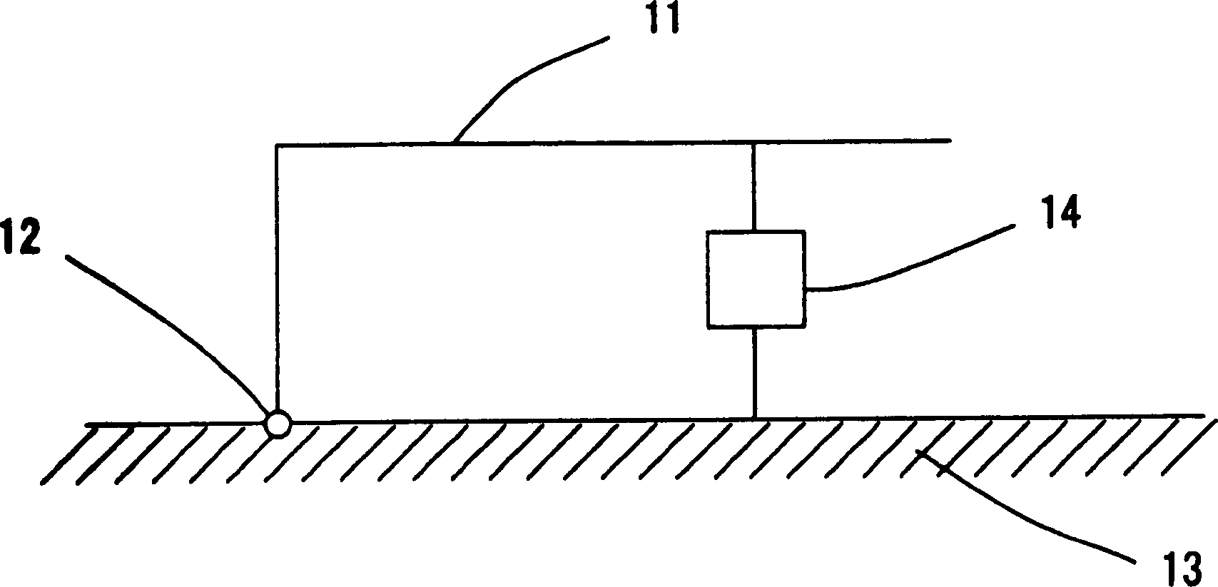
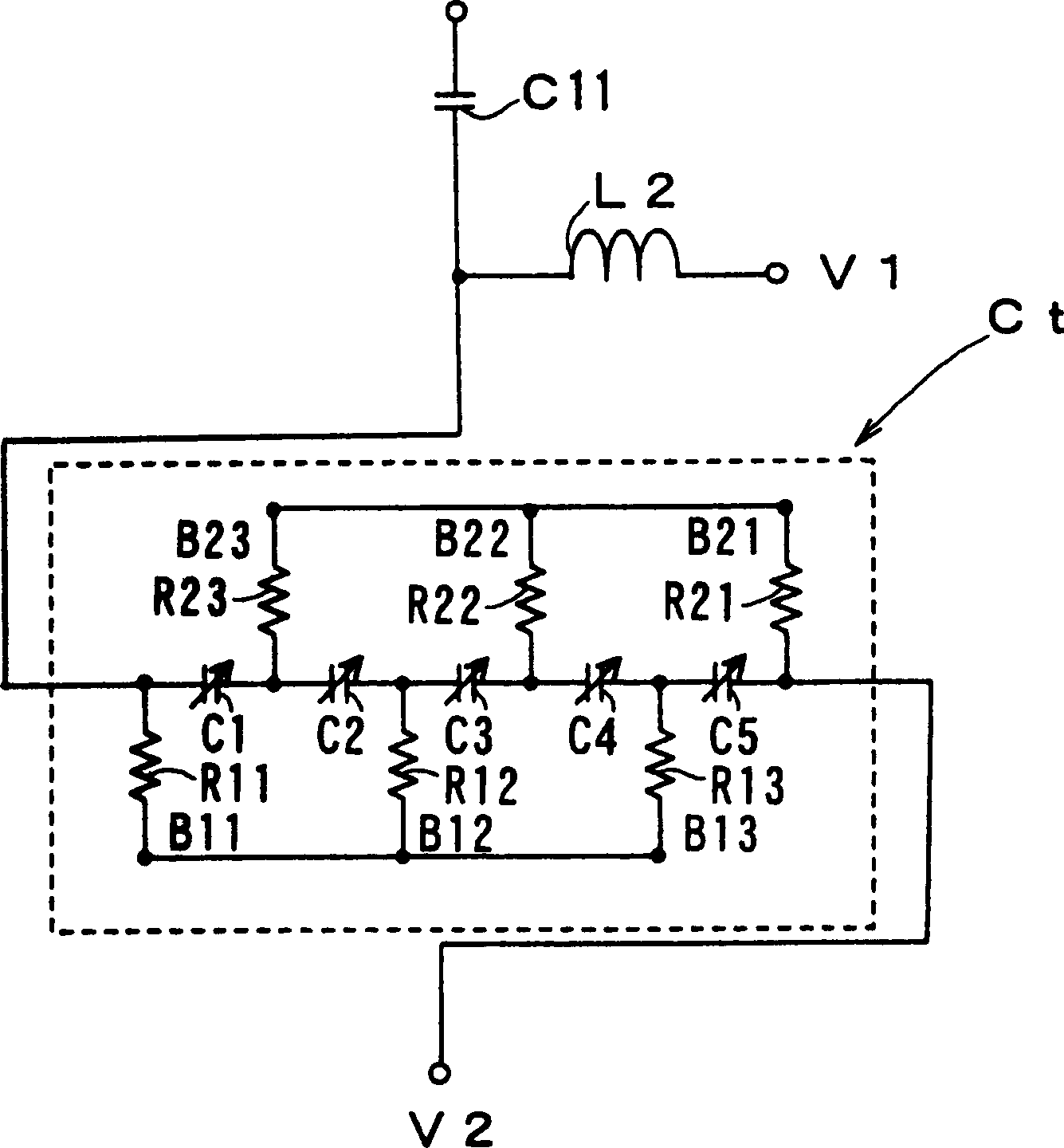
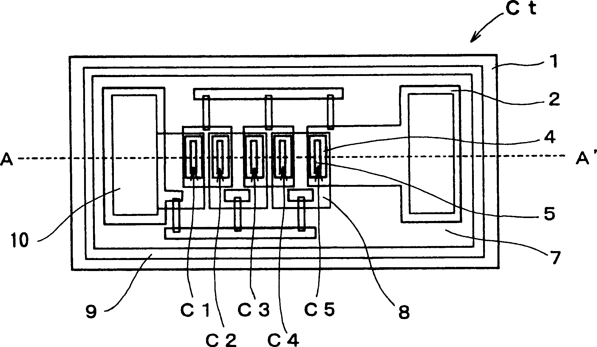
[0055] Figure 1 to Figure 5 Each shows the antenna of the first embodiment of the present invention. figure 1 It is a schematic diagram which shows the antenna of 1st Embodiment of this invention. In this example, it is a frequency variable antenna composed of an antenna element 11 composed of a conductor, a feed point 12 , a ground 13 , and a capacitance variable capacitor portion 14 . figure 2 It is an equivalent circuit diagram of the capacitance variable capacitor part. exist figure 2 In the shown equivalent circuit diagram, Ct is a capacitance variable capacitor. L2 is a yoke coil including an inductance component for RF attenuation for supplying a control voltage (bias signal), and C11 is a DC blocking capacitive element connected to the antenna element side terminal. in addition, Figure 3 ~ Figure 5 Another example of a capacitance variable c...


PUM


Abstract

An antenna is constituted in which a variable capacitance capacitor portion Ct is connected between an antenna element and a ground. In the variable capacitance capacitor, a plurality of variable capacitance elements using a thin film dielectric layer whose dielectric constant is changed by a voltage applied are connected in parallel with regard to direct current component and in series with regard to high frequency component between an antenna-element-side terminal and a ground-side terminal. The capacitance change ratio of the variable capacitance capacitor that depends on the bias signal can be utilized to the maximum so as to perform impedance matching so that the electrical length of the antenna element is changed, and thus, the operating frequency can be changed. In addition, the antenna having small waveform distortion and intermodulation distortion, high power handling capability and low loss at high frequencies can be realized.

Description

technical field [0001] The present invention relates to a withstand power that can change the electrical length of the antenna by using a variable capacitance capacitor as an antenna used in communication equipment such as a mobile phone and high-frequency components mounted on these communication equipment, and by changing its capacitance. A variable frequency antenna with excellent characteristics such as low distortion and low loss, and a wireless communication device using the antenna. [0002] The present invention relates to a variable matching circuit having a variable capacitance capacitor connected between a feed terminal of an antenna element and a feed source as an antenna device used in wireless communication of a microwave band and a millimeter wave band, and by making the capacitance variable The capacitance of the capacitor changes, so that the antenna operating frequency can be changed, and a wireless communication device using the antenna, especially an antenn...

Claims


Application Information

Patent Timeline
Patent Type & Authority Applications(China)
IPC IPC(8): H01Q9/00H01Q9/04H01Q13/00
CPCH01Q9/0442
Inventor 佐藤昭典生田贵纪
Owner KYOCERA CORP
Why Eureka
Try Eureka