Mechanism of blocking automatic fan-shaped door

A technology for blocking mechanisms and doors, applied to windows/doors, building components, building structures, etc., can solve the problems of automatic retraction and limited width setting of pedestrian passages, etc.

Active Publication Date: 2005-08-31
SHANGHAI HUAHONG JITONG SMART SYST
View PDF0 Cites 37 Cited by
  • Summary
  • Abstract
  • Description
  • Claims
  • Application Information

AI Technical Summary

Problems solved by technology

[0005] The technical problem to be solved by the present invention is to provide an automatic fan door blocking mechanism, which aims to solve the problem that it cannot be automatically retracted when the power is off, it is easy to be forcibly retracted by improper external force, and it is ineffective in setting the width of the pedestrian passage. limited defect

Method used


Image

  • Mechanism of blocking automatic fan-shaped door
  • Mechanism of blocking automatic fan-shaped door
  • Mechanism of blocking automatic fan-shaped door

Examples


Embodiment Construction

[0016] Below in conjunction with accompanying drawing and specific embodiment the present invention is described in further detail:

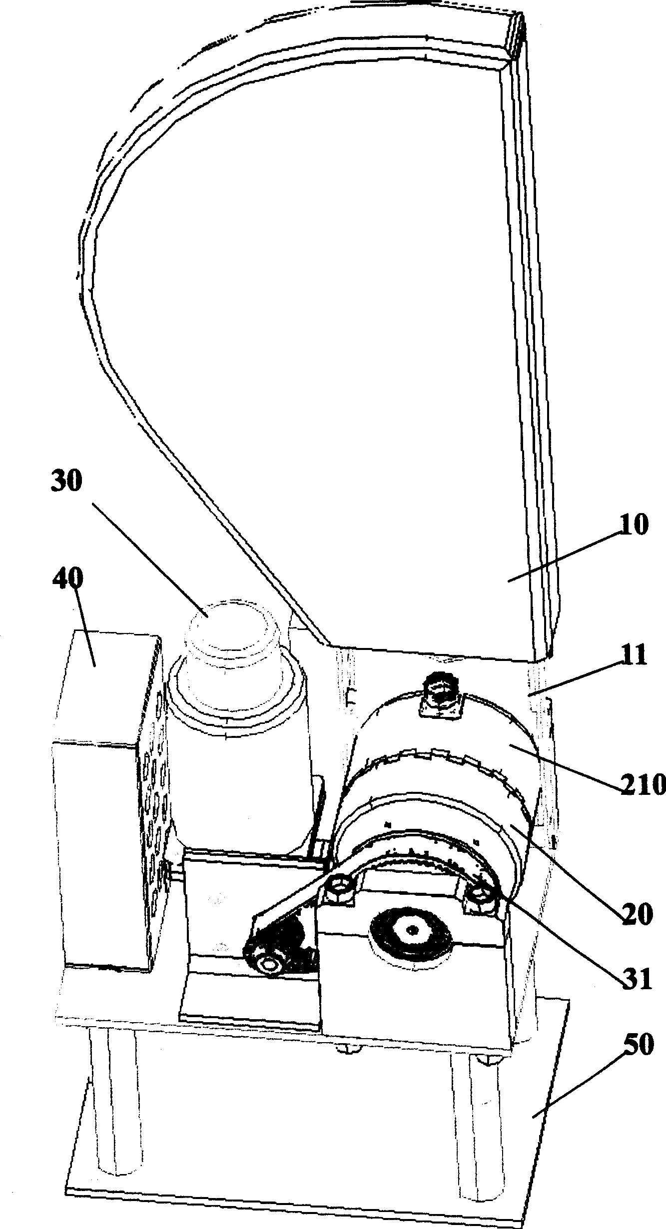
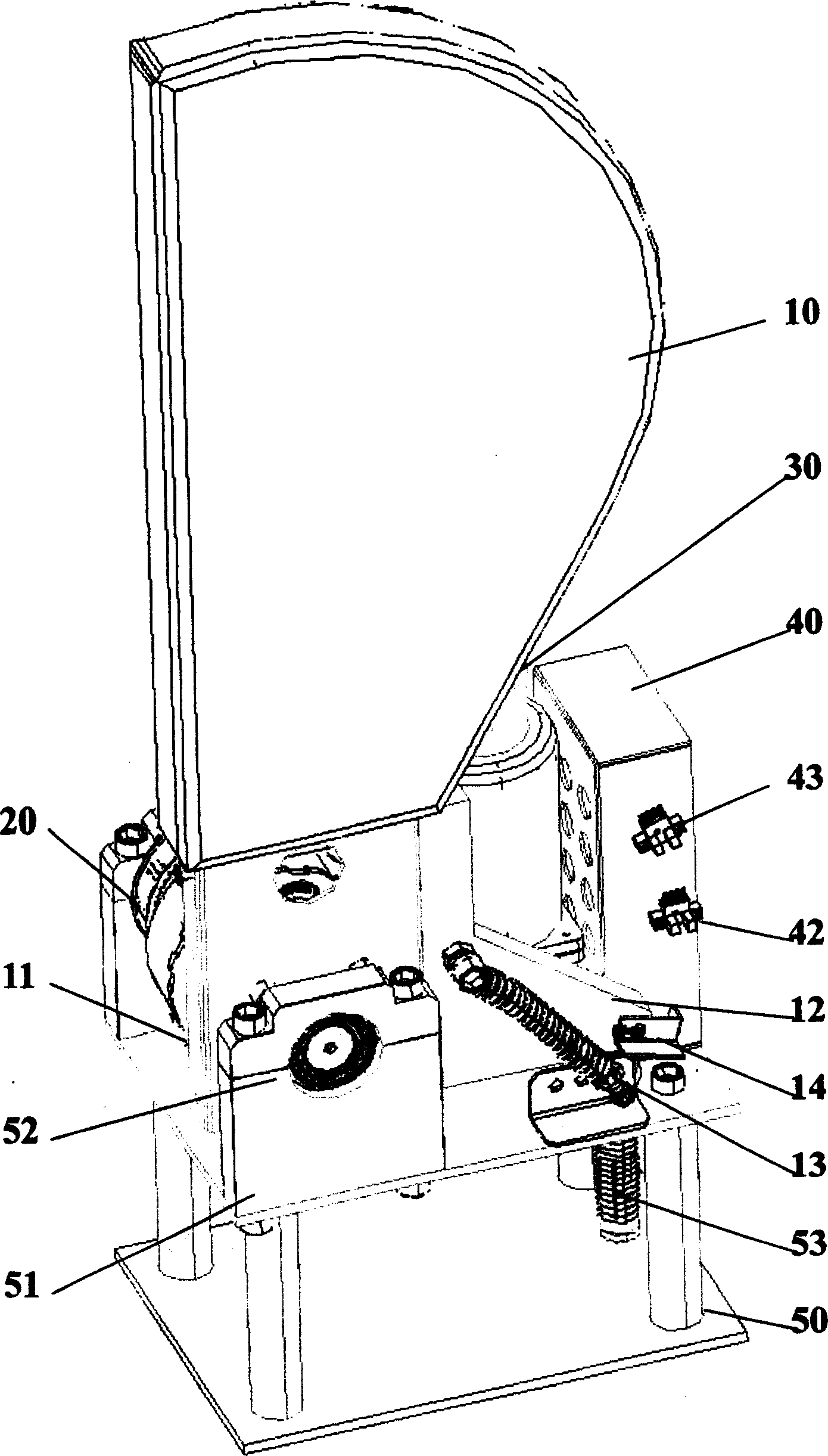
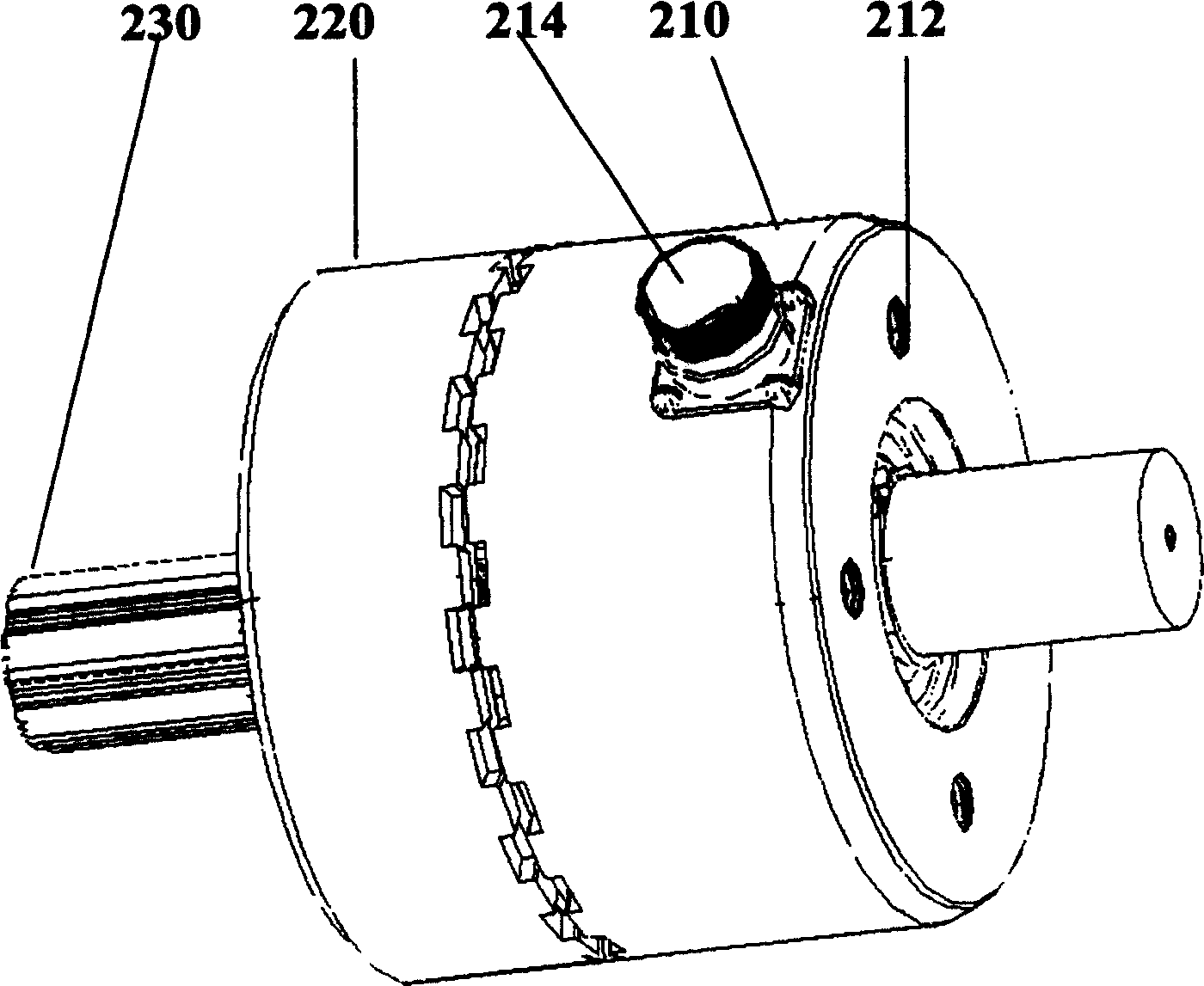
[0017] Depend on figure 1 , figure 2 , image 3 , Figure 4 It can be seen that the present invention includes a rubber door leaf 10 that can swing around an axis; it also includes a jaw electromagnetic clutch 20, a DC worm gear motor 30, an electrical control device 40, and a mounting bracket 50; the lower end of the rubber door leaf 10 that can swing around an axis is connected to The jaw electromagnetic clutch 20 is connected; the DC worm gear motor 30 for controlling the rotation of the jaw electromagnetic clutch 20, the electrical control device 40 for controlling the angle of the rubber door leaf 10 that can swing around the shaft, and the jaw electromagnetic clutch 10 fixed on the mounting bracket 50;

[0018] The lower end of the rubber door leaf 10 that can swing around the shaft is linked with the driven clutch disc 210 of the jaw...


PUM


Abstract

An automatic blocking mechanism of door leaf is featured as connecting rubber door leaf swing around shaft to electromagnetic jaw clutch, setting DC speed reducing motor and angle control device on installation base. The blocking mechanism can be switched no automatically to avoid the door leaf to be operated by outside force when electric power is off.

Description

technical field [0001] The invention relates to an automatic fare collection system at rail transit stations, in particular to a door blocking mechanism used on automatic ticket gates for entering and exiting stations. Background technique [0002] On the urban rail transit automatic ticket gate, a blocking device must be used to control the passage of passengers. [0003] At present, there are two types of trident stoppers and door leaf stoppers that are often used. Because the door-type barrier has the characteristics of fast pedestrian passing, it has been widely used in automatic ticket gates at rail transit stations. [0004] Door-type stoppers are divided into three types: vertical-axis rotating flapping doors, telescopic sliding doors, and horizontal-axis swinging leaf doors. Among them, the biggest defect of flapping doors and sliding doors is that they cannot be retracted automatically when the power is off, which is not conducive to emergency flow of people. Howe...

Claims


Application Information

Patent Timeline
Patent Type & Authority Applications(China)
IPC IPC(8): E06B11/00G07B15/04
Inventor 王融立
Owner SHANGHAI HUAHONG JITONG SMART SYST
Why Eureka
Try Eureka