Device preventing U-shaped lock rod from being cut off and both ends of lock body from being smashed and protecting lock hole

A lock body and lock rod technology, applied in padlocks, building locks, construction and other directions, can solve the problems of difficult processing, high difficulty, and difficult to prevent technical opening, etc.

Pending Publication Date: 2019-06-14
王伟
View PDF0 Cites 0 Cited by
  • Summary
  • Abstract
  • Description
  • Claims
  • Application Information

AI Technical Summary

Problems solved by technology

[0005] However, so far, because the U-lock's locking rod is relatively thin, the thick one is difficult to process, so the U-lock's locking rod is easily cut off by strong shears or hydraulic shears, and it is difficult to prevent this destructive opening method. , there are many U-shaped locks on the market, in front of the hydraulic shears that are used to stealing, there is nothing like this
[0006] Judging from the published patents under the E05b category of the Patent Office, among the hundreds of patents, some of them are related to anti-shearing, but they only claim that the use of hard materials is more anti-shearing; almost none of them mention anti-smashing; There are a few cases, but most of them are waterproof and dustproof, and some are tool-proof. Generally speaking, A-level lock cylinders are actually difficult to prevent technical opening, such as side post locks, blade locks and some special-shaped lock cylinders. On the contrary, it is more difficult to open it technically, but there is actually no evidence for those with the above-mentioned comprehensive protection functions.

Method used


Image

  • Device preventing U-shaped lock rod from being cut off and both ends of lock body from being smashed and protecting lock hole
  • Device preventing U-shaped lock rod from being cut off and both ends of lock body from being smashed and protecting lock hole
  • Device preventing U-shaped lock rod from being cut off and both ends of lock body from being smashed and protecting lock hole

Examples


Embodiment Construction

[0042] In order to further illustrate the principle and structure of this patent, the preferred embodiments of this patent will be described in detail in conjunction with the accompanying drawings. However, the described embodiments are only for illustration and explanation, and cannot be used to limit the scope of protection of this patent.

[0043] The preferred embodiment of this patent is now described:
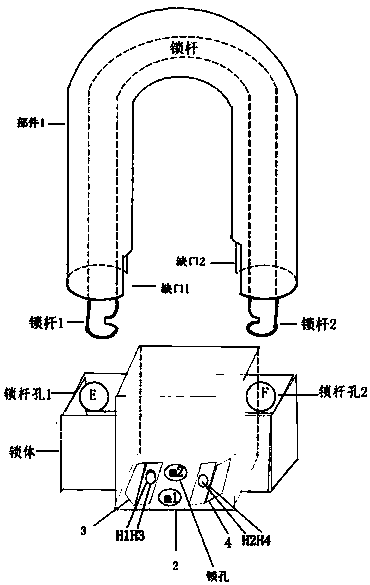
[0044] when locked,

[0045] 1) Put the short square tube with part 2 on the lock body first;

[0046] 2) Insert the lock rod with part 1 into the lock body and lock it.

[0047] As mentioned above, the device designed and conceived in this scheme has a simple and practical structure and a simple principle, and is suitable for popularization.

[0048] Specifically, only the use of part 1 can have the function of anti-shearing and part of the function of preventing the end of the lock body from being smashed; as adding parts 2, 3 and 4, it can also have part of the keyho...


PUM


Abstract

The invention relates to a device for strengthening and improving the anti-theft performance of a U-shaped lock. According to the technical scheme, the device has the purposes that 1, in order to prevent a U-shaped lock rod from being cut off, a steel pipe of 32 mm sleeves the lock rod with the diameter being 13 mm of the U-shaped lock, and a thick protective suit is worn on the lock rod to prevent the lock rod from being cut off; 2, small U-shaped gaps are formed in the two ends of the steel pipe correspondingly, the two ends of a lock body can right be arranged in the gaps to be protected against being smashed, the two ends of the lock body and the lock rod are not prone to being directly hit and taken off by destructive violence, but the two ends of traditional U-shaped lock bodies areprone to being smashed; and 3, after parts 1, 2, 3 and 4 are combined, the small space distance can be formed between a lock cylinder of a lock hole and the part 2, the difficulty of stable control ofhands to 'a pin' when the pin controlling locking tools needs to lean against the edge of the lock hole for prying off during technical unlocking is increased, if all security doors are provided withlock protection devices, the difficulty of suspended prying off is much larger, and when the device is used with a class C lock cylinder or a blade lock cylinder, the protection action is better.

Description

technical field [0001] The technical field involved in the patent proposal is the technical field of safety protection of U-shaped locks. Specifically, relate to a kind of protection device that is specially used to prevent the locking bar of U-shaped lock from being cut off by hydraulic shears. Background technique [0002] U-shaped lock is a very widely used anti-theft product, but there are many methods and tools to open it without a key, generally there are technical unlocking and destructive unlocking. All are to reach illegal unlocking, implement the purpose of stealing property, here mainly refer to be used for locking bicycle, two-wheeled or three-wheeled electric vehicle and motorcycle, and a lot of U-shaped locks that are used for locking glass door. [0003] Problems and shortcomings of U-locks, their reasons, and problems encountered in solving these problems: [0004] Due to the widespread dissemination of various unlocking technologies and methods in modern s...

Claims


Application Information

Patent Timeline
IPC IPC(8): E05B67/22E05B67/38
Inventor 王伟
Owner 王伟
Why Eureka
Try Eureka