Movement guide rail of machine tool

A motion and guide rail technology, applied in the field of machine tools, can solve the problems of adding springs, impossible, and existing errors, and achieve the effect of preventing yaw and simple structure.

Inactive Publication Date: 2005-09-07
WEIHAI HUADONG AUTOMATION
View PDF0 Cites 2 Cited by
  • Summary
  • Abstract
  • Description
  • Claims
  • Application Information

AI Technical Summary

Problems solved by technology

However, it is actually impossible to obtain complete parallelism between the reference plane of the action direction and the parallel plane on which the pressing mechanism acts, and there are errors
Moreover, springs cannot be added to the pressing mechanism due to functional and rigid reasons. Therefore, it is inevitable to leave a gap between the movable body and the parallel surface.

Method used


Image

  • Movement guide rail of machine tool
  • Movement guide rail of machine tool
  • Movement guide rail of machine tool

Examples


Embodiment Construction

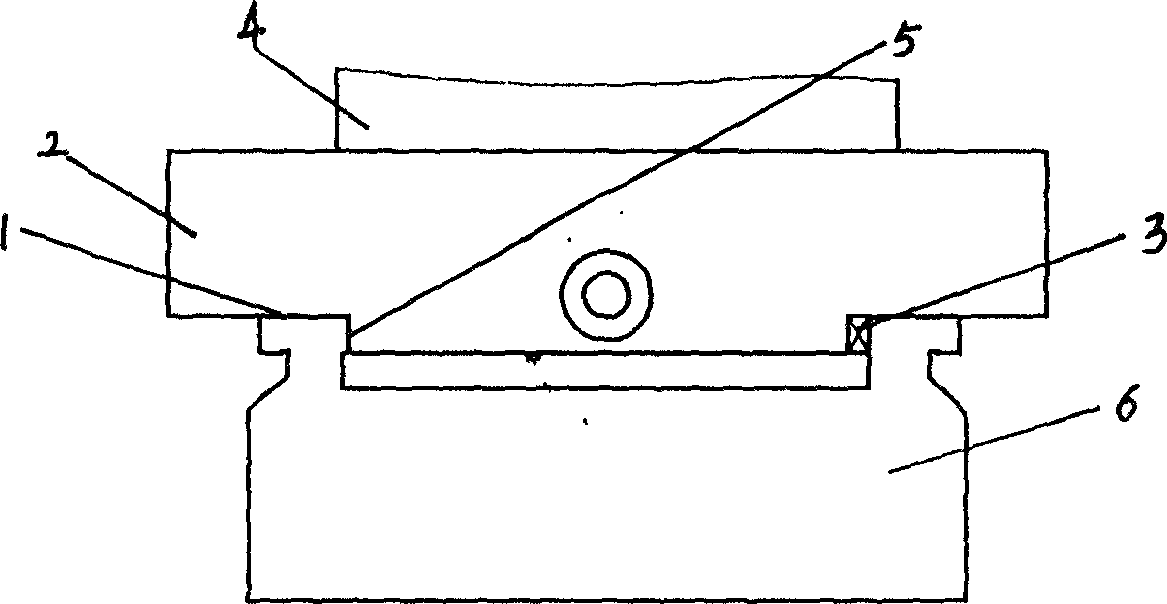
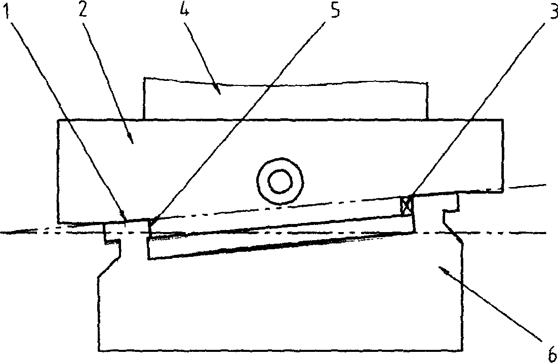
[0011] exist figure 2 Among them, the movable body 2 and the main body 6 are slidably matched through the main body, the reference surface, and the guide rail, and the workpiece 4 is placed above the movable body 2, and the upper end surface of the main body 6 that is in contact with the lower end surface of the movable body 2 is the gravity direction reference Surface 1, there is an included angle greater than zero between the reference plane 1 in the direction of gravity and the horizontal plane, the contact surface in the moving direction of the movable body is the reference plane 5 in the moving direction, and a pressing device 3 is installed between the movable body 2 and the body 6, The pressing device 3 is a wedge with an inclined surface.

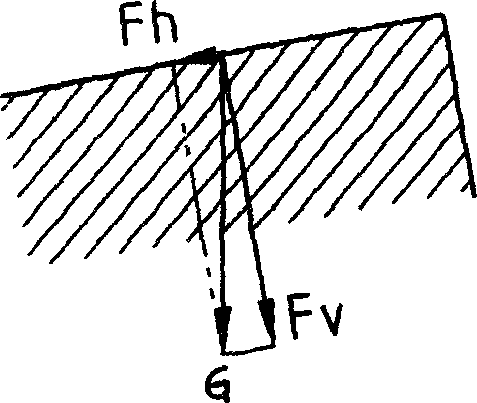
[0012] like image 3 The force analysis diagram of the reference plane 1 in the direction of gravity is shown. Gravity G is decomposed into forces in two directions, one is the component force Fh parallel to the reference plane 1 ...


PUM


Abstract

The invention relates to a kinematical guide of the machine tool, and belongs to the tool field. It has the body matching the slippage and the movable body. The basic face and the horizontal face of the body and the movable body decline an angle along the gravity direction. When the movable body sliding along the basic face, the invention can effectively prevent the movable body create out-beat, and it has the simple structure.

Description

technical field [0001] The invention relates to the field of machine tools, in particular to a motion guide rail for machine tools. Background technique [0002] The machine tool has three motion axes of X, Y, and Z, and each movable body moves along each motion reference plane. Typical motion guide rails are as follows: figure 1 As shown, there is a motion reference plane in the direction of gravity and a motion reference plane in the action direction. In order for the sliding surface of the movable body to feed precisely along the respective reference planes, the movable body and the reference plane need to be in close contact. The reference plane in the direction of gravity is parallel to the reference plane in the direction of action. For the reference plane in the direction of gravity, the sliding surface in the direction of gravity of the movable body can closely fit the movement depending on the self-weight of the movable body or the weight of the workpiece carried on...

Claims


Application Information

Patent Timeline
IPC IPC(8): B23Q1/01
Inventor 大平研五秦之旭梁勇
Owner WEIHAI HUADONG AUTOMATION
Why Eureka
Try Eureka