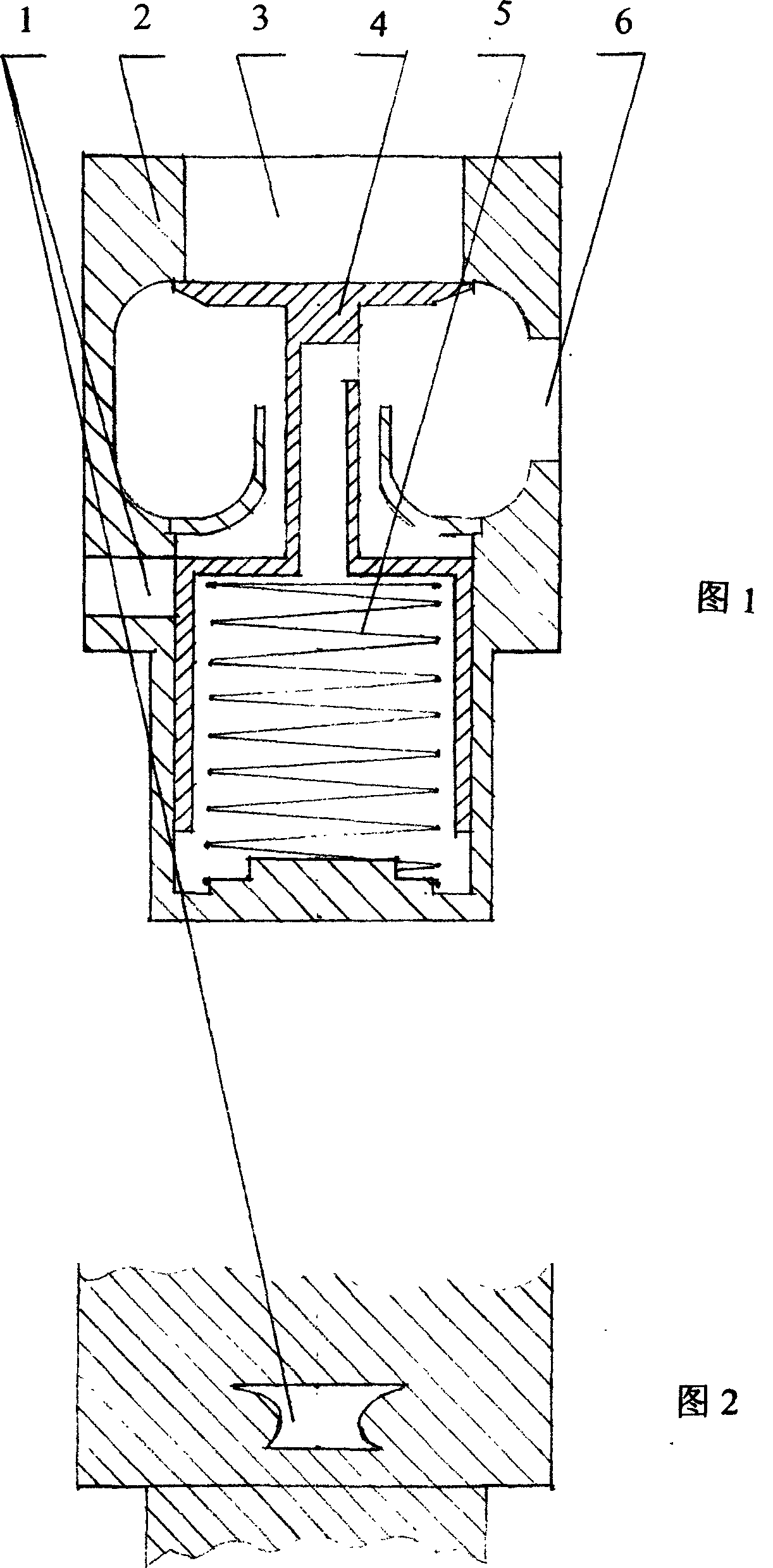
Vacuum contant pressure, mixer for internal combustion engine

An internal combustion engine and mixer technology, which is applied to internal combustion piston engines, combustion engines, engine components, etc., can solve problems such as unreasonable mixture concentration, poor idle speed performance, and incomplete combustion.

Inactive Publication Date: 2005-09-28
蒙国宁
View PDF0 Cites 4 Cited by
  • Summary
  • Abstract
  • Description
  • Claims
  • Application Information

AI Technical Summary

Problems solved by technology

[0003] The purpose of the present invention is to: increase the allowable compression ratio of the engine under the premise that the anti-knock ability of the fuel remains unchanged, improve the thermal efficiency of the fuel, and reduce the fuel consumption; Requirem...

Method used


Image

  • Vacuum contant pressure, mixer for internal combustion engine

Examples


specific Embodiment

[0014] 1. For CNG / EFI dual-purpose fuel vehicles, the engine adopts a compression ratio of 12.5:1. When the gas is used, the spring force of the constant pressure spring 5 should be reduced as much as possible, and the maximum air intake of the engine cylinder should be increased to increase the gas power. The mixer Mixing function alone; when fuel is used, increase the elastic force of the constant pressure spring 5 to control the maximum cylinder air intake of the engine, so that the maximum compression force of the cylinder meets the anti-knock ability requirements of gasoline fuel, and avoid engine knocking. Constant pressure effect.

[0015] 2. For LPG single-fuel vehicles; (1) Giving priority to power performance, adopting a compression ratio of 10:1, minimizing the elastic force of constant pressure spring 5, and the mixer only plays the role of mixing air and gas; (2) Giving priority to fuel Economical, using a compression ratio of 15:1, increasing the spring force of ...


PUM


Abstract

The constant vacuum degree mixer is used for oil burning engine, gas burning engine and oil and/or gas burning engine. Using the constant vacuum degree mixer in engine can make automobile and motorcycle saving energy by over 15 %, possessing excellent starting performance, stable idle performance, accurate gas distribution and greatly lowered exhaust pollution. The present invention has simple structure, low cost and high producibility.

Description

technical field [0001] The invention belongs to the field of internal combustion engines. Background technique [0002] Existing Venturi mixers and proportional mixers do not have the function of intake constant pressure, and cannot increase the allowable compression ratio of the engine to achieve the purpose of energy saving under the premise that the fuel antiknock ability remains unchanged; on the other hand, the two kinds of mixed The ratio of the air metering hole to the gas metering hole of the engine remains unchanged, the mixture concentration cannot change with the reasonable needs of various engine working conditions, and the contradiction between the power and economy of the engine's high and low speed is prominent, resulting in some working conditions Incomplete combustion, poor economy, poor emissions, difficulty in starting a small-displacement motorcycle, and unstable idle speed; in order to meet the needs of the engine air intake, th...

Claims


Application Information

Patent Timeline
IPC IPC(8): B60K15/10F02M21/04
CPCY02T10/32Y02T10/30
Inventor 蒙国宁
Owner 蒙国宁
Why Eureka
Try Eureka