Image display equipment with deficient picture removing function

An image display device and afterimage technology, which is applied in image communication, color TV parts, TV system parts, etc., can solve problems affecting product reliability, heat generation, product overheating, etc. Effect

Inactive Publication Date: 2005-09-28
NANJING LG TONGCHUANG COLOR DISPLAYS SYST CO LTD
View PDF0 Cites 2 Cited by
  • Summary
  • Abstract
  • Description
  • Claims
  • Application Information

AI Technical Summary

Problems solved by technology

[0015] However, in the conventional method of image afterimage removal, the maximum output value is continuously output until the end signal is input by the user, so the image display device will consume the maximum power for a long time, and the power consumption will continue to increase; as a result, the product will overheat , and due to overheating, will cause heat generation, or will affect product reliability

Method used


Image

  • Image display equipment with deficient picture removing function
  • Image display equipment with deficient picture removing function
  • Image display equipment with deficient picture removing function

Examples


Embodiment Construction

[0028] Next, referring to the drawings, the implementation of the present invention will be described in detail.

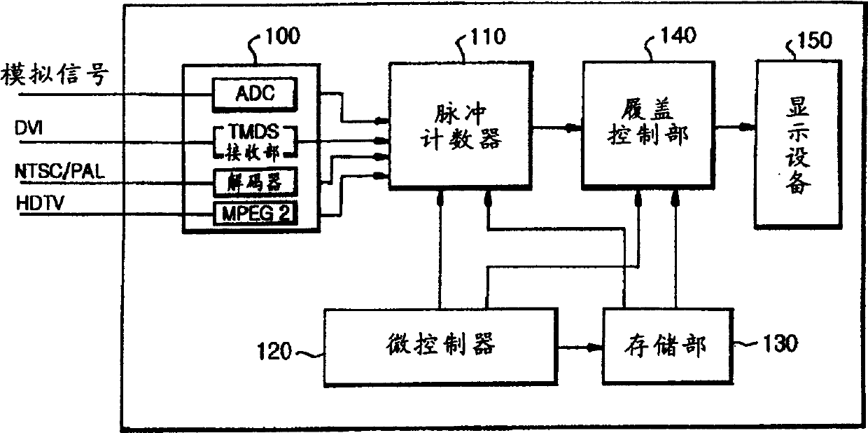
[0029] The image afterimage elimination method of the present invention is very suitable for image display devices using PDP display screens.

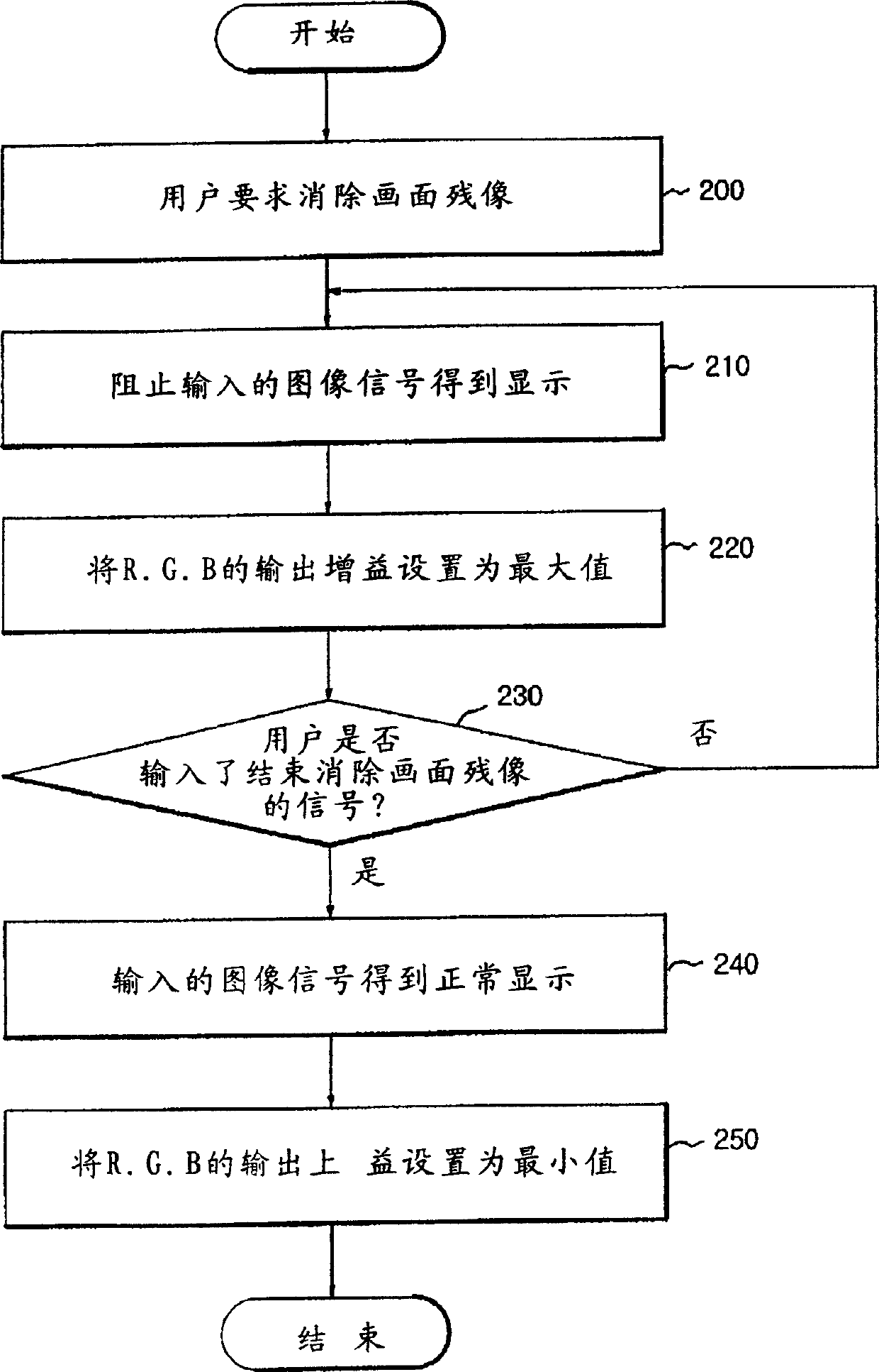
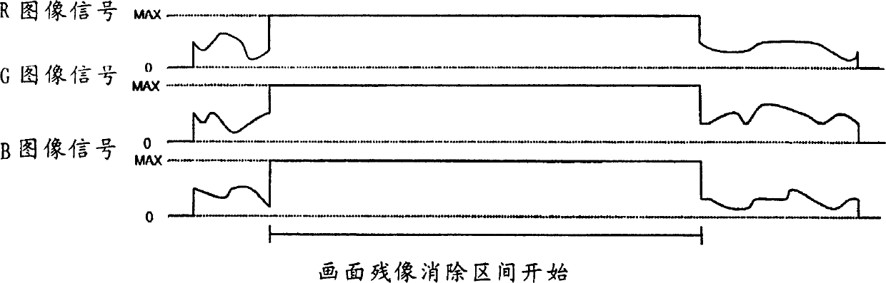
[0030] Referring to FIG. 4, it can be seen that firstly, the continuous operation mode for the image afterimage removal function is set and saved, that is, stage 400; the continuous operation mode is preferably composed of more than one mode. As shown in FIG. 5, in the example of FIG. 5, the continuous operation mode is composed of N times. Also according to each operation mode, output gain values ​​of red, green and blue (R, G, B) image signals are respectively set. At this time, it is preferable to set the output gain value of the red, green and blue image signals to the maximum value (FFh) in the first operation mode. After completing the setting operation of the continuous operation mode, save it.

[0031] Then, whe...


PUM


Abstract

The present invention relates to an image display equipment with the function capable of eliminating picture residual image and its method. Said method includes the following several stages: stage for setting a series of continuous operation modes for eliminating picture residual image; stage for inputting an execution instruction for eliminating picture residual image; storage for cutting off inputted image signal which is outputted from storage portion; stage for successively executing set continuous operation modes to eliminate picture residual image; stage for displaying normally-inputted image if the above-mentioned continuous operation modes are completed. Said invention equipment includes various devices for implementing above-mentioned all the stages.

Description

[0001] Field [0002] The present invention relates to a method for eliminating image afterimages in image display devices. In more detail, the present invention relates to a method for removing afterimages by using a timer to change the signal output level at regular time intervals. Background technique [0003] Next, the configuration of a general image display device will be briefly described with reference to FIG. 1. FIG. [0004] As shown in Figure 1, the image display device is composed of the following parts: a signal input unit 100 is provided to convert various image signals input from the outside into a signal state suitable for the display device; The resolution of the image signal transmitted by 100 is converted into a pulse counting section 110 consistent with the resolution of the display device section; a microcontroller 120 for controlling the entire operation process is provided; a storage section 130 for storing image signals or data is provided ; An overla...

Claims


Application Information

Patent Timeline
Patent Type & Authority Applications(China)
IPC IPC(8): H04N5/14
Inventor 申在允
Owner NANJING LG TONGCHUANG COLOR DISPLAYS SYST CO LTD
Why Eureka
Try Eureka