Liquid display device and method for driving liquid crystal display device

A technology of a liquid crystal display device and a driving method, which can be applied to static indicators, instruments, etc., and can solve problems such as different, inability to optically compensate for black display, and reduced contrast

Inactive Publication Date: 2005-10-05
JAPAN DISPLAY CENTRAL CO LTD
View PDF0 Cites 13 Cited by
  • Summary
  • Abstract
  • Description
  • Claims
  • Application Information

AI Technical Summary

Problems solved by technology

[0012] That is, there is a problem in the liquid crystal display device using the conventional OCB mode. When the temperature increases, even in the case of black display, optical compensation cannot be performed to display black brightly, and the contrast ratio is lowered.
[0013] In addition, there is a problem in the liquid crystal display device using the conventional OCB mode that when the temperature changes, the actual display brightness is different from the intended display brightness.

Method used


Image

  • Liquid display device and method for driving liquid crystal display device
  • Liquid display device and method for driving liquid crystal display device
  • Liquid display device and method for driving liquid crystal display device

Examples


no. 1 Embodiment approach

[0061] First, the first embodiment will be described.

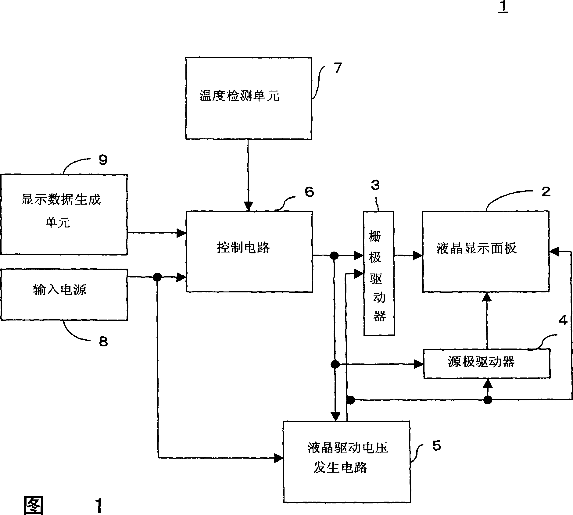
[0062] FIG. 1 is a block diagram of a liquid crystal display device 1 according to the first embodiment.

[0063] The liquid crystal display device 1 is a liquid crystal display device using OCB mode liquid crystal.

[0064] The liquid crystal display device 1 is composed of a liquid crystal display panel 2, a gate driver 3, a source driver 4, a liquid crystal drive voltage generating circuit 5, a control circuit 6, a temperature detecting unit 7, an input power source 8, and a display data generating unit 9.

[0065] The liquid crystal display panel 2 has source signal lines and gate signal lines arranged in a matrix, and a liquid crystal display panel provided at the intersection of the source signal lines and the gate signal lines and using liquid crystal display elements of OCB mode liquid crystal.

[0066] The gate driver 3 is a circuit that supplies selective scanning signals for line-sequential scanning on the respecti...

no. 2 Embodiment approach

[0099] Next, the second embodiment will be described.

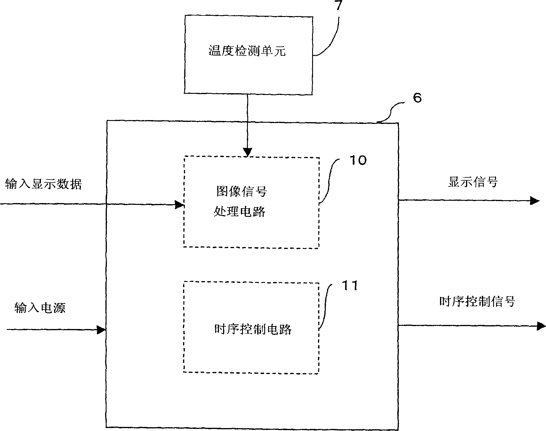
[0100] FIG. 6 shows a block diagram of the liquid crystal display device 12 according to the second embodiment.

[0101] The liquid crystal display device 12 is a liquid crystal display device using OCB mode liquid crystals as in the first embodiment.

[0102] The liquid crystal display device is composed of a liquid crystal display panel 2, a gate driver 3, a source driver 4, a liquid crystal drive voltage generating circuit 13, a control circuit 14, a temperature detection unit 7, and an input power source 8. In addition, the second embodiment also includes the same display data generating circuit as that of the first embodiment 1, but it is not shown for simplicity.

[0103] The liquid crystal display device 12 of the second embodiment is different from the liquid crystal display device of the first embodiment in the control circuit and the liquid crystal drive voltage generating circuit 13.

[0104] That is, the control c...


PUM


Abstract

A liquid crystal display device includes a liquid crystal display panel having source signal lines and gate signal lines arranged in matrix form and liquid crystal display elements using OCB mode liquid crystal, the liquid crystal display elements being provided at intersections between the source signal lines and gate signal lines; a gate driver that supplies a gate signal to said gate signal lines; a source driver that supplies a voltage corresponding to gradation of display data to said source signal lines during a display period; temperature detection means of detecting temperature; and correcting means of correcting display data for generating the source signal to display data according to the detected temperature, wherein the source signal is generated based on the corrected display data.

Description

Technical field [0001] The present invention relates to a liquid crystal display device using OCB mode liquid crystal, and a driving method of the liquid crystal display device. Background technique [0002] As a replacement for the past picture tube, the liquid crystal display device is thin and light, and its use is increasing in recent years. However, the widely used TN (Twisted Nematic) orientation liquid crystal panel has a small viewing angle, a very slow response speed, and tailing when displaying dynamic pictures, and the image quality is not as good as a picture tube. [0003] On the contrary, in recent years, an OCB (Optically Compensated Bend) mode liquid crystal display device with high-speed response and wide viewing angle has been widely used. The liquid crystal display device bends orientates the liquid crystal and performs visual compensation, and also obtains a wide viewing angle by combining it with an optical phase compensation film. [0004] Fig. 12 shows a sc...

Claims


Application Information

Patent Timeline
Patent Type & Authority Applications(China)
IPC IPC(8): G02F1/133G09G3/36
CPCG09G3/3651G09G3/3655G09G3/3696G09G2320/0276G09G2320/041G09G2320/066G09G2340/0428G09G3/36
Inventor 川口聖二
Owner JAPAN DISPLAY CENTRAL CO LTD
Why Eureka
Try Eureka