Method for taking computed tomography scans with the aid of a CT unit, and a CT unit

A technology of tomography and computer, which is applied in X-ray equipment, computerized tomography scanners, instruments for radiological diagnosis, etc., can solve the problem of not being able to obtain the improved scan of the inspection object, so as to avoid redundant measurement and high The effect of overscan

Inactive Publication Date: 2005-10-12
SIEMENS AG
View PDF4 Cites 10 Cited by
  • Summary
  • Abstract
  • Description
  • Claims
  • Application Information

AI Technical Summary

Problems solved by technology

[0006] Although all these documents show the basic method of the embodiment of the CT device with jumping focus, it cannot be deduced from these prior arts how the improved scan of the examination object should be used and how it should be implemented for the calculation of the CT image. Required Data Acquisition and Data Preparation

Method used


Image

  • Method for taking computed tomography scans with the aid of a CT unit, and a CT unit
  • Method for taking computed tomography scans with the aid of a CT unit, and a CT unit
  • Method for taking computed tomography scans with the aid of a CT unit, and a CT unit

Examples


Embodiment Construction

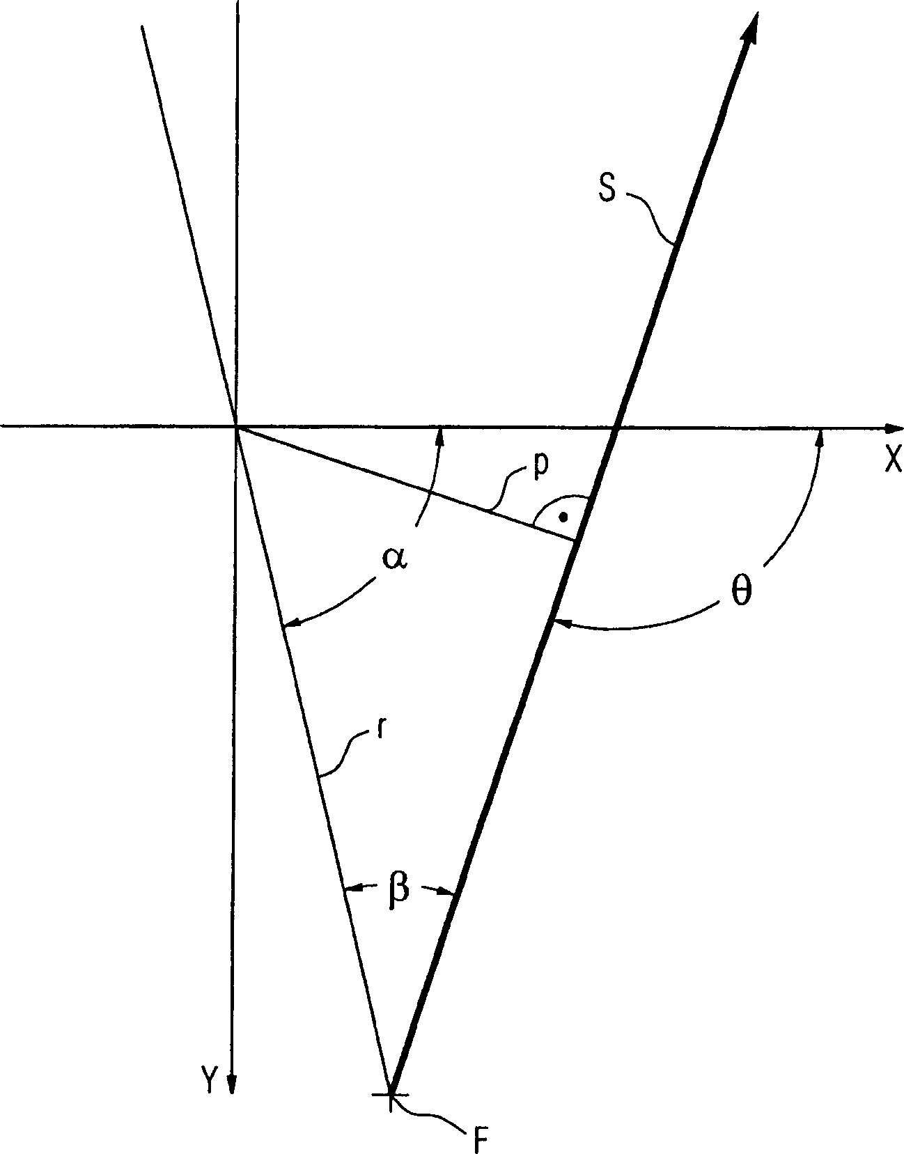
[0030] figure 1 The geometry employed in this application is shown. An x / y coordinate system is shown with the z-axis perpendicular to the x / y plane (also called the system axis of the CT apparatus) protruding from the paper at the origin. The position of the focal point F is defined by the radius from the z-axis and the rotation angle α around the z-axis. The position of the x-ray S is determined in this plane by the fan angle β and the distance p from the origin. The sector angle β between the x-axis and the x-ray S is determined in each case by the position of the focal point F and the individual detector elements observed. Furthermore, the inclination angle [phi] of the X-ray S around the x-axis is obtained from the positions of the observed detector rows and the z-position of the focal point.

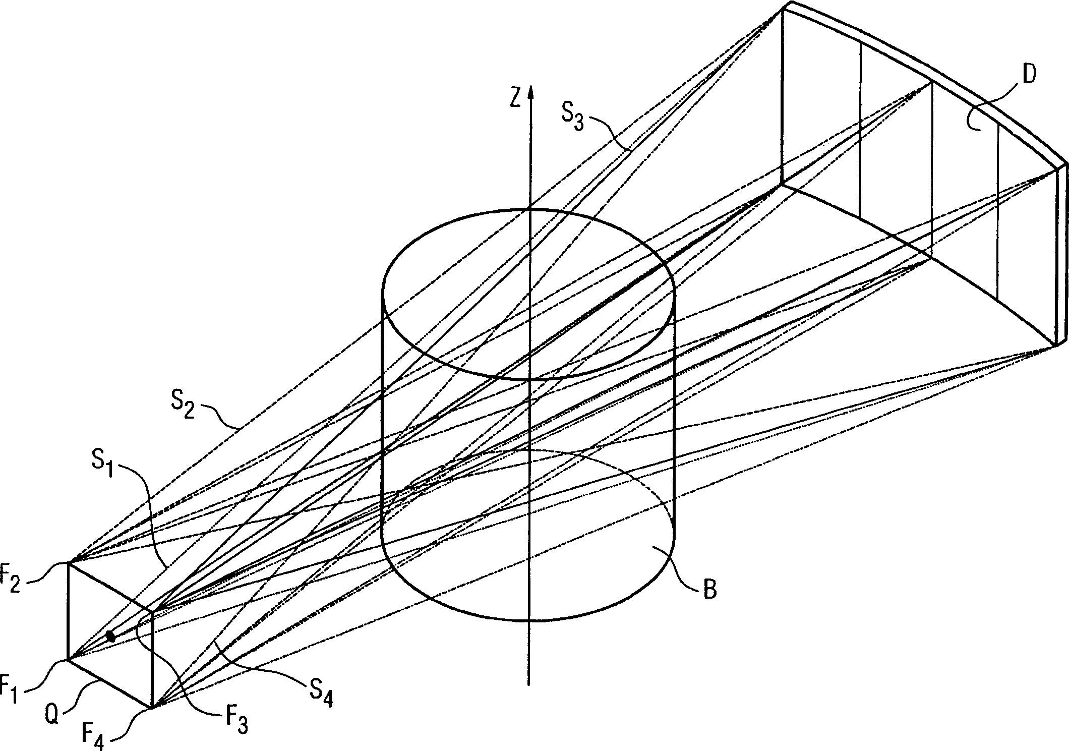
[0031] figure 2 shows the method according to the invention with 4 different focus positions F 1 to F 4 Schematic diagram of an exemplary jumping focus of , which emits X-ra...


PUM


Abstract

A method is for taking computed tomography scans with the aid of a CT unit and to a CT unit. An X-ray tube is moved in a circle or spiral about a z-axis in combination with a detector situated opposite and an object is scanned. The X-ray tube includes a jumping focus with two or more different jumping focal positions relative to the X-ray tube. Parallel data records are formed from the detector data obtained, and tomograms are reconstructed therefrom. When forming the parallel data records, account is taken of the different position of the respectively current jumping focus in relation to the X-ray tube (=jumping focal position) in the radial direction.

Description

technical field [0001] The present invention relates to a method for producing computed tomography pictures using a CT device and a CT device in which an X-ray tube and a detector arranged opposite it move in a ring or helically around the z-axis and scan an object, wherein the X-ray The tube has a jumping focus with two or more different jumping focus positions relative to the x-ray tube, from the acquired detector data a side-by-side data set is formed from which a cross-sectional image is reconstructed. Background technique [0002] Such computed tomography systems are known in patent documents US Pat. No. 5,625,661, US Pat. No. 6,256,369 B1 and utility model document DE 29923967 U1, which have an X-ray tube with a jump focus. [0003] In US Pat. No. 5,625,661 a CT device is shown in which the focal point can be jumped in the z-direction to a number of different focal positions relative to the X-ray tube, whereby multiple lines with the same relative arrangement are detec...

Claims


Application Information

Patent Timeline
Patent Type & Authority Applications(China)
IPC IPC(8): A61B6/03G01N23/00G01N23/04G01N23/06G21K1/12H05G1/08H05G1/60
CPCA61B6/4085A61B6/4028A61B6/032G01N23/046G06T11/005A61B6/027G01N2223/419
Inventor 赫伯特·布鲁德托马斯·弗洛尔卡尔·斯蒂尔斯托弗
Owner SIEMENS AG
Why Eureka
Try Eureka