Hydrodynamic bearing-type pump
A kind of dynamic pressure bearing and dynamic pressure technology, which can be used in bearings, sliding contact bearings, bearings in rotating motion, etc., and can solve problems such as lack of reliability.
Inactive Publication Date: 2005-11-02
SONY CORP
View PDF1 Cites 3 Cited by
- Summary
- Abstract
- Description
- Claims
- Application Information
AI Technical Summary
Problems solved by technology
Moreover, in the past, in order to dispose the motor inside, the outer wall of the pump is composed of a plurality of members such as the cylindrical portion 325 and the partition wall 324, so it is difficult to completely seal the connecting portion between the cylindrical portion 325 and the partition wall 324 without fluid leakage. , lack of reliability
Method used
View moreImage
Smart ImageViewing Examples
Examples
Embodiment Construction
Login to View More PUM
 Abstract
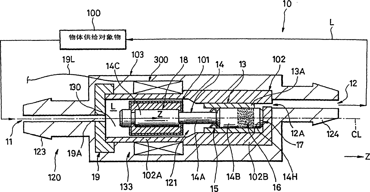
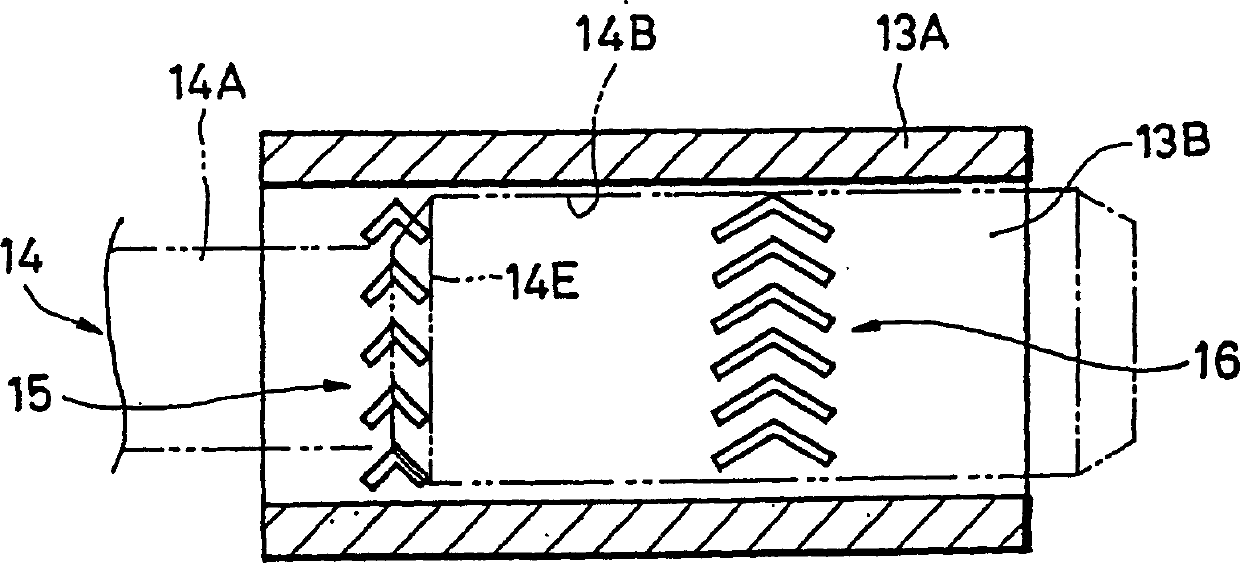
A hydrodynamic pressure bearing type pump includes a main body having a fluid flow inlet formed at one end portion thereof and a fluid flow outlet formed at the other end portion thereof and a rotating portion disposed within a fluid flow passage of the fluid within the main body to generate hydrodynamic pressure to let the fluid flow into the fluid flow inlet and to let the fluid flow from the fluid flow outlet to the outside. The rotating portion includes a shaft, a hydrodynamic pressure bearing for generating hydrodynamic pressure to let the fluid flow into the fluid flow inlet and to let the fluid flow from the fluid flow outlet to the outside when the shaft is rotated and a rotation force generating portion disposed within the main body to generate rotation force for rotating the shaft when it is energized.
Description
technical field The present invention relates to a dynamic pressure bearing type pump as a power source for discharging fluid. Background technique A pump for discharging fluid is used, for example, in an artificial heart (for example, refer to Japanese Patent Application Publication No. 6-102087, pages 3 to 5, FIG. 5 ). The above-mentioned conventional pump is shown in FIG. 6, and FIG. 7 shows the dynamic pressure bearing of the conventional pump in FIG. In FIG. 6 , a conventional pump 310 includes a dynamic pressure shaft 320 with radial and axial dynamic pressure generating grooves and a rotor magnet 322 . The dynamic pressure shaft 320 rotates integrally with the rotor magnet 322, and an armature coil 323 for driving the rotor magnet 322 is also provided in the pump partition 324. In the conventional pump 310, the dynamic pressure bearing 321 is used both as a pressure generator for pumping pressure and as a device for supporting the rotor magnet 322 in a radial an...
Claims
Login to View More Application Information
Patent Timeline
 Patent Type & Authority Applications(China)
IPC IPC(8): F04D29/046F04D3/00F04D11/00F04D13/02F04D13/06F04D29/04F04D29/047F16C17/02F16C17/04F16C33/10H02K7/08H02K7/14
CPCF04D3/00F04D29/047F04D13/0633F04D13/064F04D13/0606F04D29/04F04D13/02
Inventor 宍户祐司
Owner SONY CORP
Features
- R&D
- Intellectual Property
- Life Sciences
- Materials
- Tech Scout
- Unparalleled Data Quality
- Higher Quality Content
- 60% Fewer Hallucinations
Learn More Browse by: Latest US Patents, China's latest patents, Technical Efficacy Thesaurus, Application Domain, Technology Topic, Popular Technical Reports.
© 2025 PatSnap. All rights reserved.Legal|Privacy policy|Modern Slavery Act Transparency Statement|Sitemap|About US| Contact US: help@patsnap.com


