Displaying method and apparatus for changing display position according to external environment

A technology of a display device and a display method, which is applied in the directions of transportation and packaging, vehicle components, image data processing, etc., can solve the problems of not showing a graphic display, the ability of the display device to present a visually recognizable graphic display, etc.

Inactive Publication Date: 2005-12-14
DENSO CORP
View PDF1 Cites 13 Cited by
  • Summary
  • Abstract
  • Description
  • Claims
  • Application Information

AI Technical Summary

Problems solved by technology

[0004] However, such a display device does not show graphic display (display) according to the environmental conditions outside the vehicle.
As a result, i

Method used


Image

  • Displaying method and apparatus for changing display position according to external environment
  • Displaying method and apparatus for changing display position according to external environment
  • Displaying method and apparatus for changing display position according to external environment

Examples


Embodiment Construction

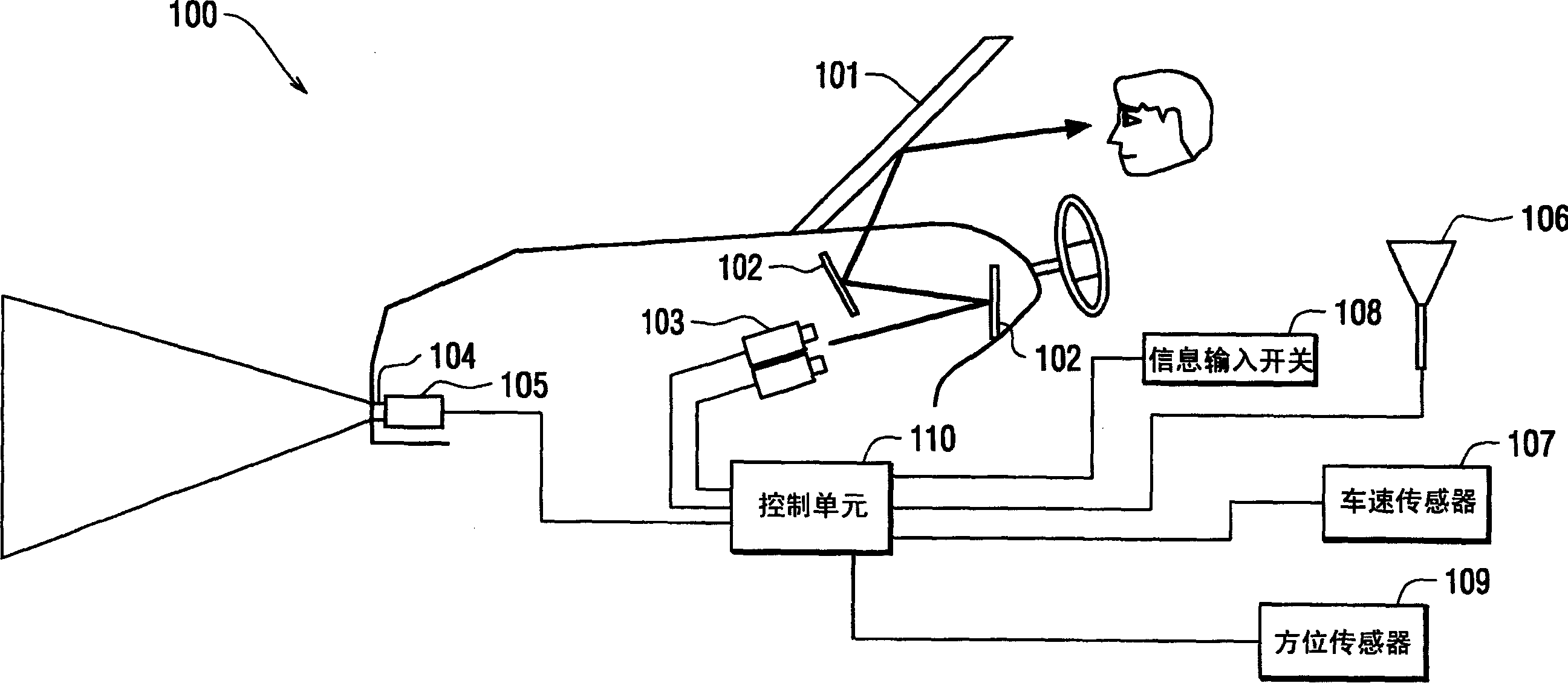
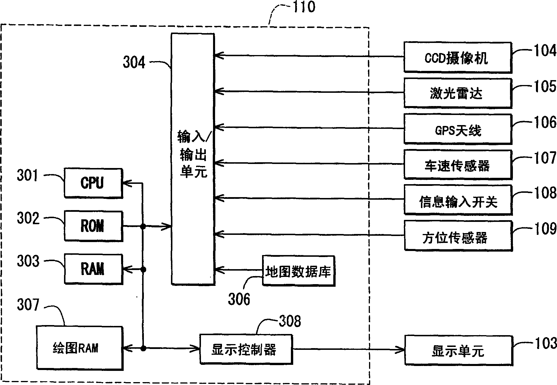
[0032] First refer to figure 1 , the navigation system 100 includes: a windshield 101, a mirror 102, two display units 103, a CCD camera 104, a laser radar 105, a GPS antenna 106, a vehicle speed sensor 107, an information input switch 108, an orientation sensor 109 and a control unit 110.

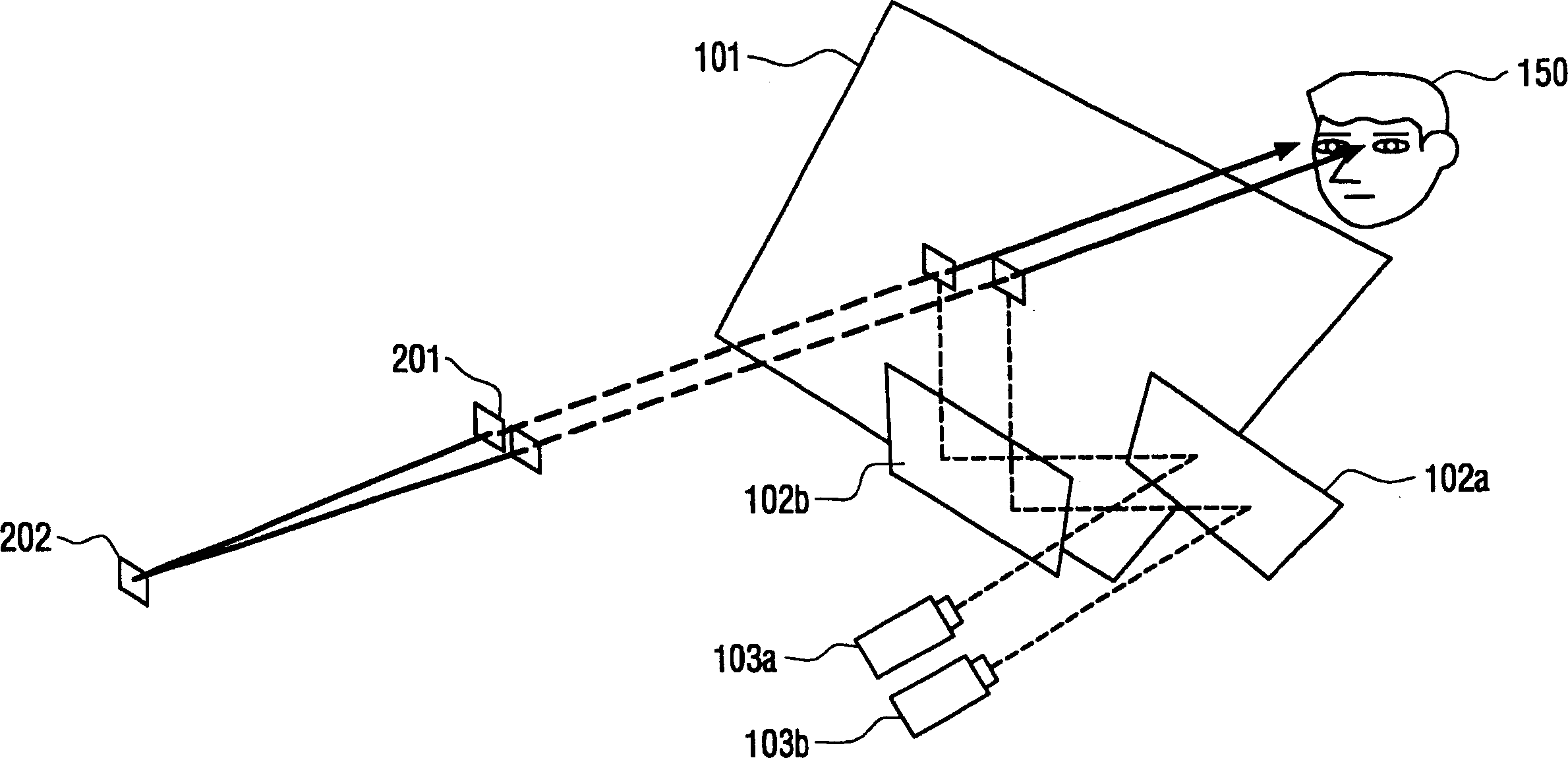
[0033] The windshield 101 is a vehicle front window. The windshield 101 is surface-treated on its inner surface (ie, on the cab side) so that it can be used as a combiner. The mirror 102 is a mirror that guides the light beam output from the display unit 103 to the windshield 101 . Display units 103 are provided for the driver's left and right eyes, respectively. The light beams output by the display unit 103 are guided to the driver's left and right eyes by the mirror 102 and the windshield 101 .

[0034] The CCD camera 104 is an optical camera for taking pictures of the front view in front of the vehicle. The CCD camera 104 can output a picture image as an electrical signal. The las...


PUM


Abstract

In the planer display device, when there is some front vehicle exists between the movable information transmission device and the vehicle, the movable information transmission device is shifted to one other position to distinguish information, so as to obtain the information hidden behind the front vehicle. The present invention can obtain the results of lowering the incoordination feeling of the driver and getting more information.

Description

technical field [0001] The invention relates to a display method for presenting information to a driver of a vehicle, and also to a display device employing the method. Background technique [0002] As a display method for presenting information to a vehicle driver, various methods have been proposed. One of the conventional methods is a heads-up display (HUD). Such a HUD device is characterized in that the HUD can reduce the amount of movement of the user's point of view, and thus is useful for improving safety. [0003] In order to improve display visual recognizability of the HUD device, a display device disclosed in Japanese Patent No. 2,913,901 has been proposed that utilizes a visual difference between eyes of a driver. According to this display device, the visual difference, the amount and the position of the displayed data are changed according to the change of the traveling position of the vehicle, thereby improving driver's perception and improving safety. [00...

Claims


Application Information

Patent Timeline
IPC IPC(8): B60R99/00G06T19/00
Inventor 柏田真司中村耕治安藤浩藤川卓之柿崎胜
Owner DENSO CORP
Why Eureka
Try Eureka