Steam valve

A steam valve, main steam technology, applied in the direction of machine/engine, mechanical equipment, engine components, etc., can solve problems such as difficulty in suppressing pressure loss

Active Publication Date: 2005-12-14
KK TOSHIBA
View PDF1 Cites 9 Cited by
  • Summary
  • Abstract
  • Description
  • Claims
  • Application Information

AI Technical Summary

Problems solved by technology

[0022] Thus, with the known combination steam valve, it is difficult to suppress the pressure loss caused by factors such as secondary flow, mixing loss, etc.

Method used


Image

  • Steam valve
  • Steam valve
  • Steam valve

Examples


no. 1 example

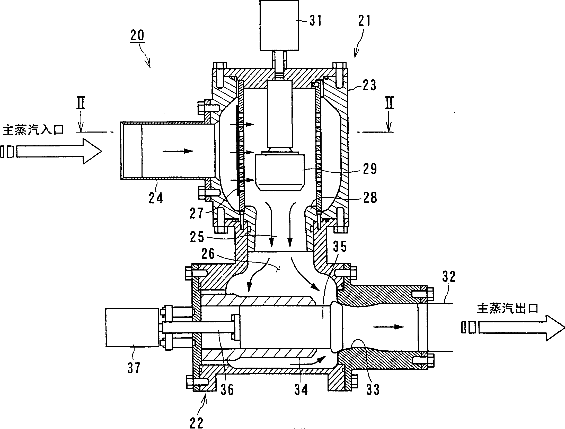
[0161] For the first embodiment, the steam valve 20 includes a main steam stop valve and a steam control valve (steam flow regulating valve) combined with each other, wherein the first valve device 21 corresponding to the main steam stop valve is arranged on the upstream side of the main steam flow, The second valve device 22 corresponding to the steam control valve (steam flow regulating valve) is arranged on the downstream side of the main steam flow, and further, the first valve device 21 and the second valve device 22 are accommodated in one valve housing 23 .

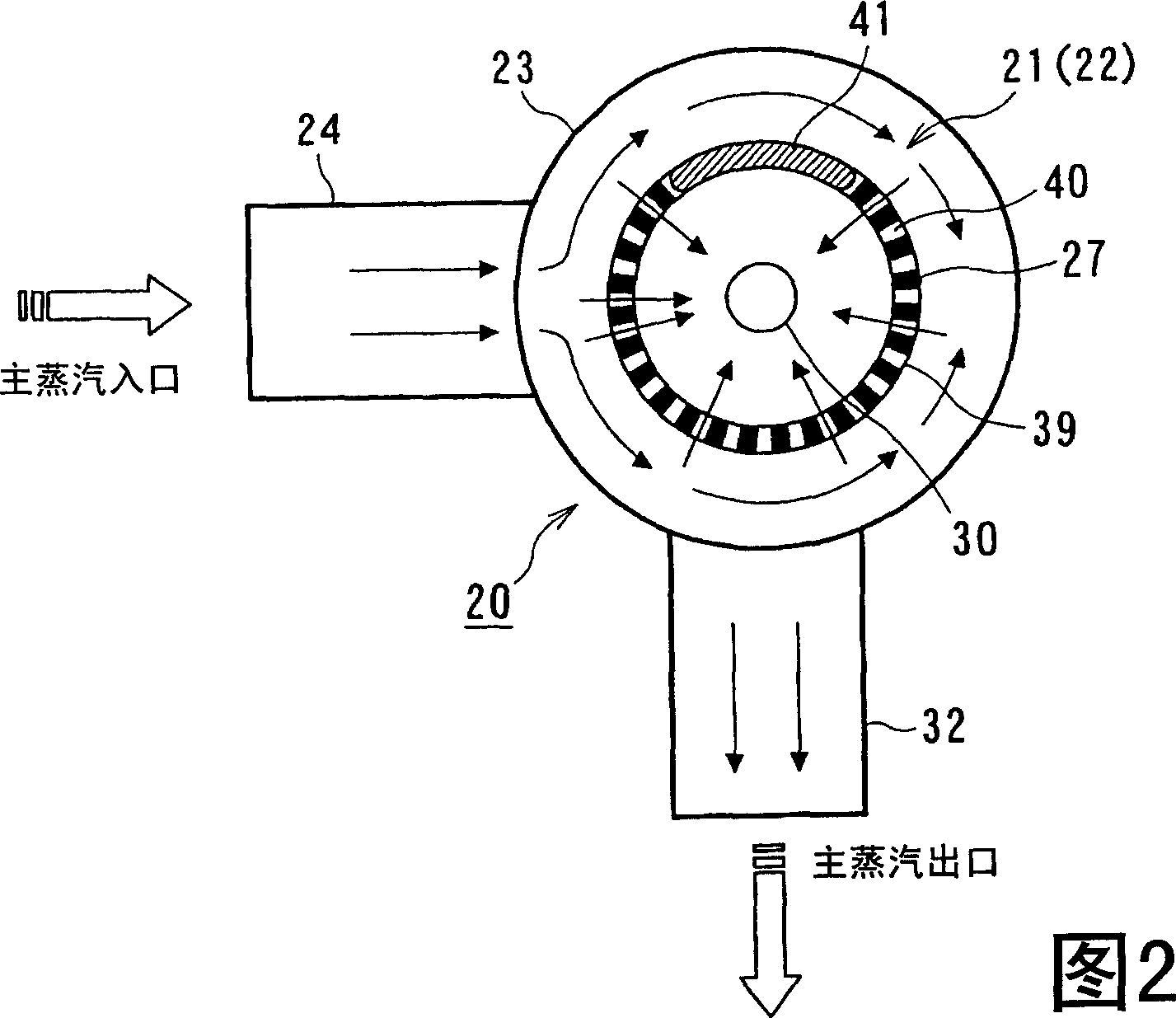
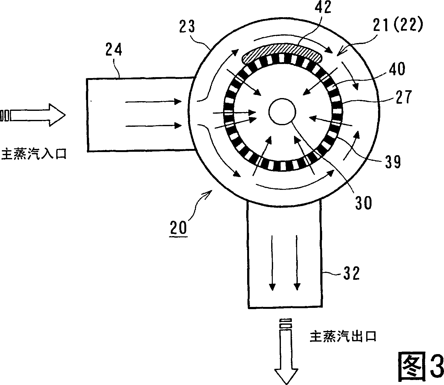
[0162] The first valve device 21 is provided with a first main steam inlet 24 and a first main steam outlet 25 connected to a second main steam inlet 26 of the second valve device 22 in the valve housing 23, and the first valve device 21 accommodates A filter 27 for removing impurities such as scale and the like.

[0163] In addition, the first valve device 21 is provided with a first valve body 29 and a first driv...


PUM


Abstract

The steam valve according to the present invention is such a steam valve that accommodates: a first valve device 21 including a valve seat, a valve body, a valve stem and a driving device, a first valve device 21 including a valve seat, a valve body, a valve rod and a driving device Two valve devices 22, which are combined with each other in the valve body 23, and prevent a part of the main steam flow from the outside of the filter into the inside of the closing portion 41 are formed in the filter housed in the valve housing 23 and surround the valve body 29 of the first valve device. device 27. According to the above structure, by effectively controlling the flow of steam in the filter accommodated in the valve case, it is possible to provide the steam valve for the purpose of further reducing the pressure loss.

Description

technical field [0001] The present invention relates to a steam valve for a steam turbine plant, and in particular to an improvement of a steam valve combining a main steam stop valve and a steam control valve (steam flow regulating valve). technical background [0002] Typically, many steam turbine installations have what is known as a three-cylinder axial-flow type configuration, in which the high-pressure steam turbine, intermediate-pressure steam turbine, and low-pressure steam turbine are directly connected to the shaft of the turbine rotor so that the generator generates as much load as possible (output ). [0003] A steam turbine device having a three-cylinder axial-flow type structure is provided to accommodate a plurality of turbine stages in which turbine nozzles and turbine blades are combined in each of a high-pressure steam turbine, an intermediate-pressure steam turbine, and a low-pressure steam turbine in the axial direction of a turbine rotor inside the case...

Claims


Application Information

Patent Timeline
Patent Type & Authority Applications(China)
IPC IPC(8): F01D17/10
Inventor 大友文雄大石勉新关良树福山佳孝松田寿进藤藏
Owner KK TOSHIBA
Why Eureka
Try Eureka