Frame connecting structure

A technology for connecting structures and frames, applied in the direction of connecting components, rods, furniture, etc., can solve problems such as inconvenient operation and unsightly appearance, and achieve a complete and beautiful appearance

Inactive Publication Date: 2006-01-11
特乐家具(上海)有限公司 +1
View PDF0 Cites 4 Cited by
  • Summary
  • Abstract
  • Description
  • Claims
  • Application Information

AI Technical Summary

Problems solved by technology

The connection between the uprights and the uprights that make up the frame, or between the frame and the frame, is mostly connected by screws and nuts in the traditional way, and the nail heads and nuts are exposed, which is neither beautiful nor convenient to operate.

Method used


Image

  • Frame connecting structure
  • Frame connecting structure
  • Frame connecting structure

Examples


Embodiment Construction

[0015] Embodiments of the present invention will be described below in conjunction with the accompanying drawings, so as to make the structural details, features, objectives and advantages of the present invention more clear, but not intended to limit the scope of the present invention.

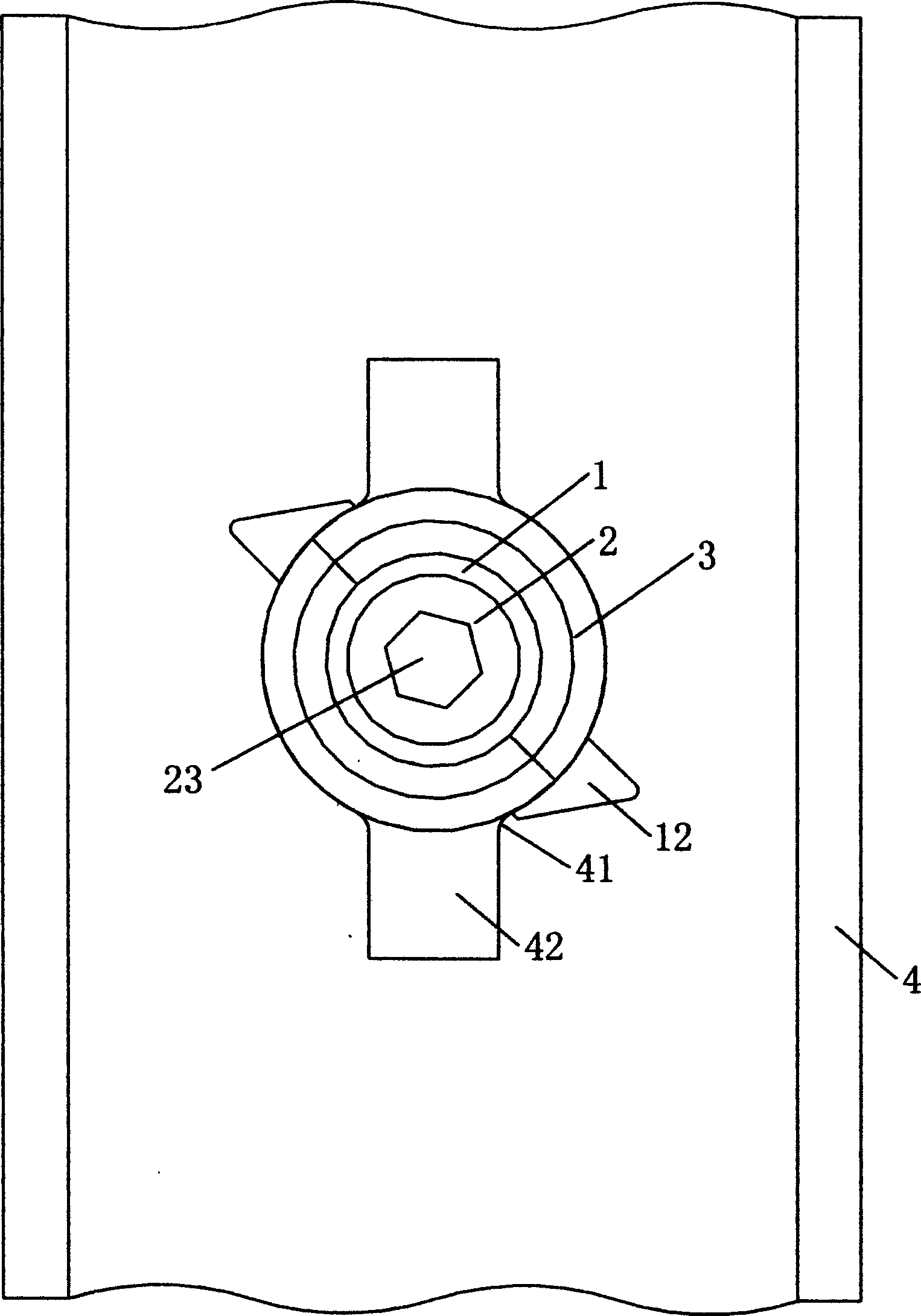
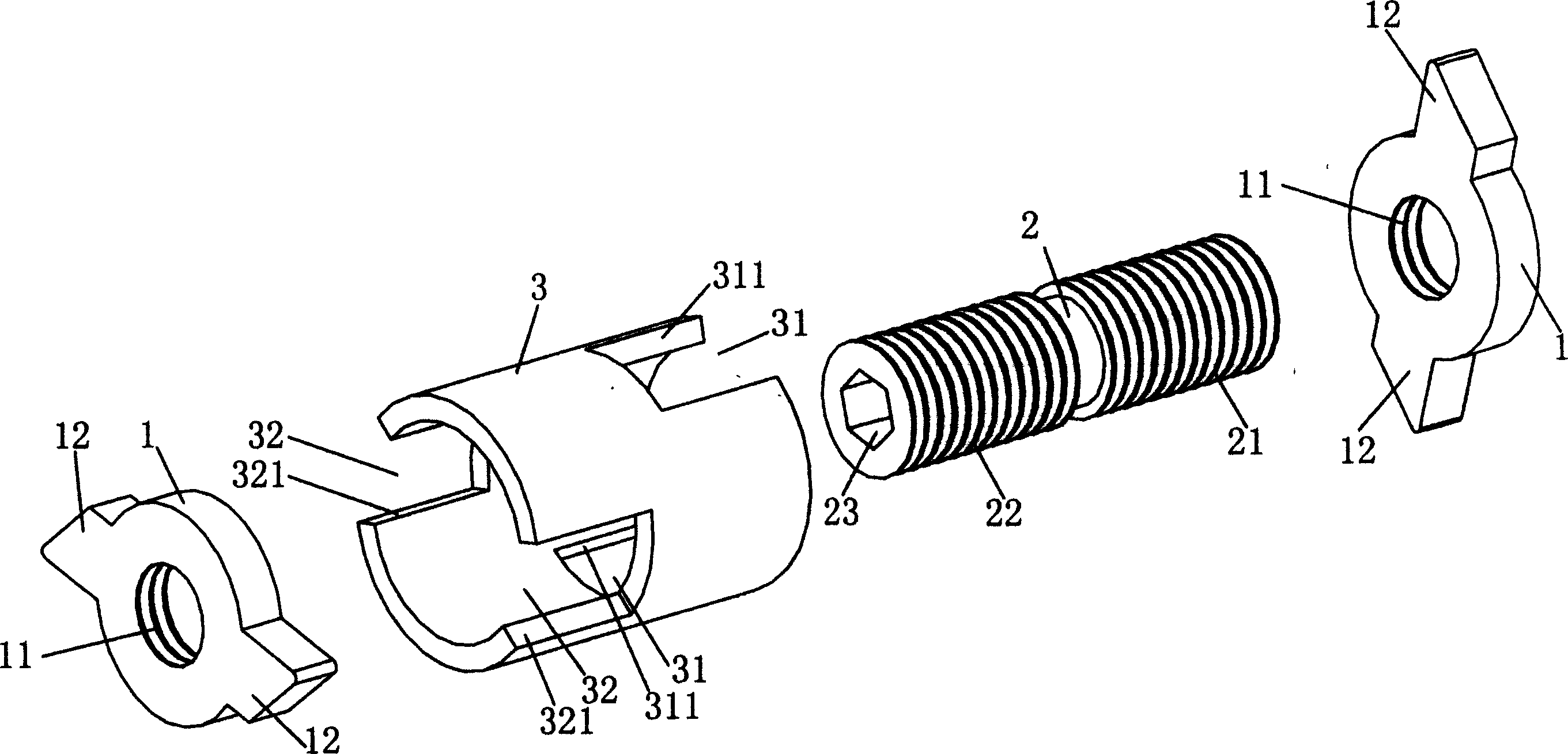
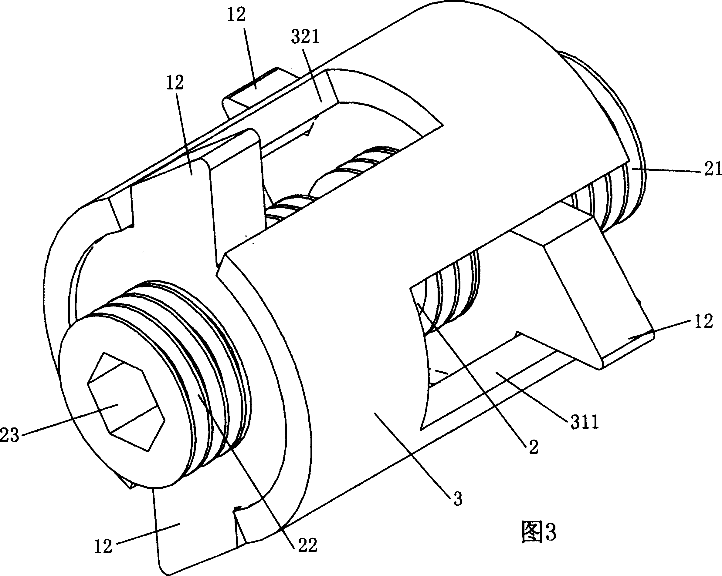
[0016] Now illustrate the structure of the embodiment of the present invention in conjunction with accompanying drawing: as figure 1 and 2 As shown, a frame connection structure is composed of upright columns 4 constituting the frame and connectors. The connectors such as figure 2 As shown, it consists of a connecting rod 2, two pressing pieces 1 and a cylindrical shell 3. The connecting rod 2 has double-start threads 21 and 22 with opposite helical directions, and a recess 23 in the shape of an inner triangle, inner square or inner hexagon is respectively provided at both ends of the connecting rod 2 . The center of the pressing piece 1 is provided with a screw hole 11 matching the screw...


PUM


Abstract

A frame-jointing structure comprises a column and a fitting. A jointing rod forming the fitting has a double-thread screw, at each end of which is screwed a press piece. The jointing rod and two pressure pieces are fixed in a cylindrical casing, and the ends of which are mounted. A group of notches are disposed at the ends of the casing. A pair of symmetrical extension lugs disposed in the extended position of two sides of the press piece extend respectively to the outside of the notches at one end of the casing and can slide in the notches. The holes disposed on the column matching with the fitting can make the fitting pass through.

Description

Technical field [0001] The invention relates to a connection mechanism for furniture decoration, and more particularly to a frame connection structure. Background technique [0002] With the development of society and the continuous improvement of people's living standards, most modern office spaces are open and large rooms, but each employee has a relatively independent activity area. When partitioning, prefabricated columns can be used to form a frame, and then decorative panels can be placed on the frame to randomly divide into spaces of required size for collective office use. The connection between the uprights and uprights of the frame, or between the frame and the frame, is mostly connected by screws and nuts in the traditional way, and the nail heads and nuts are exposed outside, which is neither beautiful nor convenient to operate. Contents of the invention [0003] The purpose of the present invention is to provide a convenient connection structure utilizing the...

Claims


Application Information

Patent Timeline
Patent Type & Authority Applications(China)
IPC IPC(8): F16B12/00F16B7/18E04B2/76
Inventor 吴炳洲
Owner 特乐家具(上海)有限公司
Why Eureka
Try Eureka