Controlled artificial intervertebral disc implant

A technique for intervertebral discs and vertebrae used in the field of devices for treating spinal injuries and diseases

Inactive Publication Date: 2006-01-18
SYNTHES GMBH
View PDF0 Cites 19 Cited by
  • Summary
  • Abstract
  • Description
  • Claims
  • Application Information

AI Technical Summary

Problems solved by technology

[0014] Although each of the prostheses described above solves some of the problems rela

Method used


Image

  • Controlled artificial intervertebral disc implant
  • Controlled artificial intervertebral disc implant
  • Controlled artificial intervertebral disc implant

Examples


Embodiment Construction

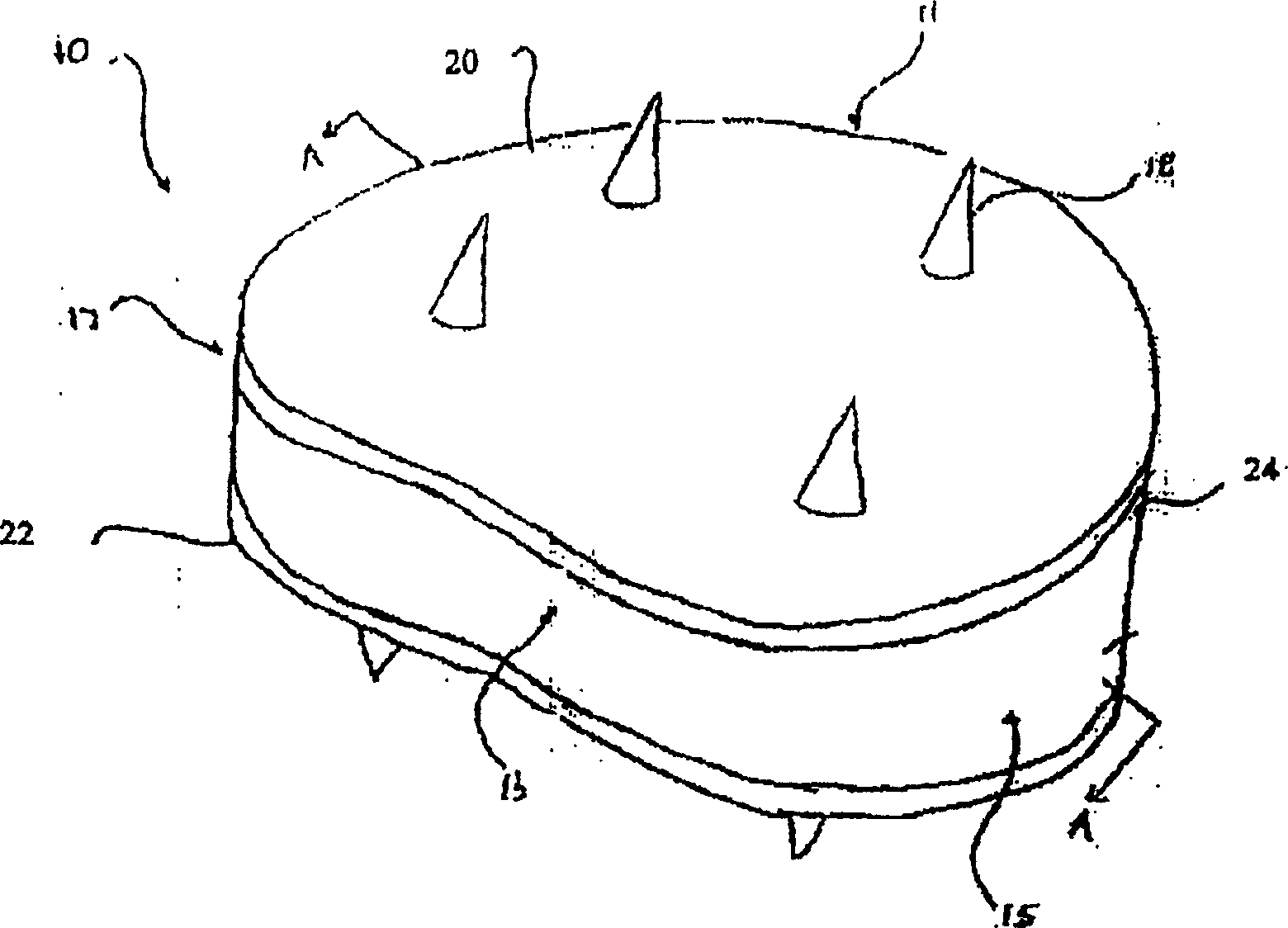
[0055] Any of a variety of different implant configurations can be prepared according to the teachings shown in the illustrative intervertebral disc examples disclosed herein. The discs of the present invention are preferably designed to restore normal spinal curvature (or sagittal balance), disc height, allow normal range of motion, absorb shock and provide resistance to motion and axial compression.

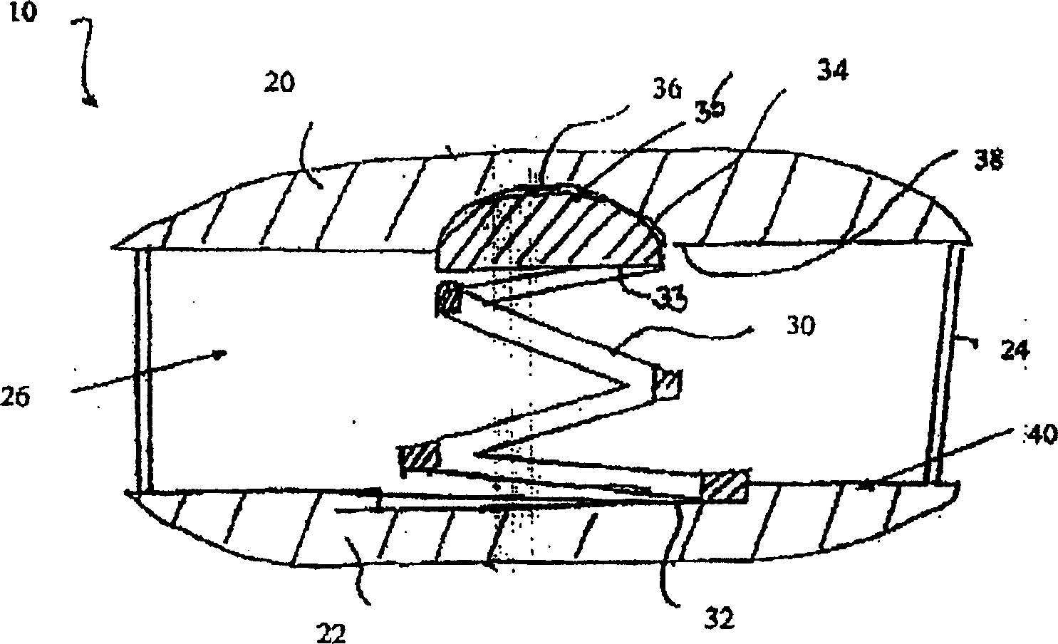
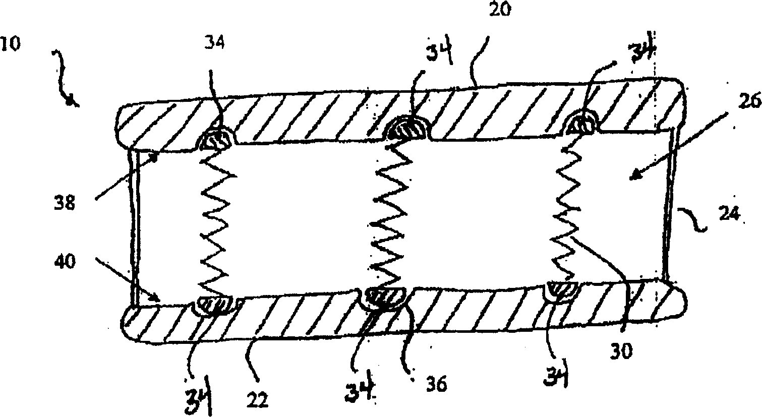
[0056] The discs are best sized and applied to the cervical, thoracic, and lumbar regions of the spine. The disc can also be customized for each individual patient, making the performance of the disc suitable for the individual patient. For example, an artificial disc can be provided with a pair of endplates and a core, and the core of the disc can include different components, different components, and / or various types of materials to create the desired dynamic properties for each individual patient.

[0057] Also, the intervertebral disc allows for flexion, extension, latera...


PUM


Abstract

The invention relates to an artificial intervertebral disc for placement between adjacent vertebrae. The artificial intervertebral disc is preferably designed to restore disc height and lordosis, allow for a natural range of motion, absorb shock and provide resistance to motion and axial compression. Furthermore, the intervertebral disc may be used in the cervical, the thoracic, or the lumbar regions of the spine. The artificial intervertebral disc may include either singularly or in combination: an interior at least partially filled with a fluid; a valve for injecting fluid into the interior of the disk; a central region having a stiffness that is preferably greater than the stiffness of the cuter regions thus enabling the disc to pivot about the central region. The central pivot may be formed by a center opening, a central chamber, an inner core or a central cable.

Description

technical field [0001] The present invention relates to devices and methods for treating spinal injuries and diseases. More specifically, the present invention relates to intervertebral disc replacement. Background technique [0002] Conditions such as detached vertebrae, herniated discs, spinal nerve root compression, degenerative disc disease and injuries are known to cause severe discomfort requiring medical treatment. Spinal fusion is one of the methods currently used to alleviate these conditions, such as intervertebral and posterolateral fusion or arthrodesis. In these methods, two adjacent vertebral bodies are fused together. The diseased disc is first removed, followed by the insertion of an implant that accommodates bone growth between the two vertebrae to effectively bridge the gap left by the disc's removal. A number of different implant materials and implant designs have been used for fusion with varying success. Although intervertebral and posterolateral fus...

Claims


Application Information

Patent Timeline
IPC IPC(8): A61F2/44
CPCA61F2/30742A61F2/30767A61F2/30965A61F2/441A61F2/4425A61F2/4455A61F2/4611A61F2002/30004A61F2002/30565A61F2310/00023
Inventor 大卫·格伯贾斯廷·K·科珀斯克里斯托弗·M·安吉卢奇大卫·保罗帕斯卡尔·斯蒂尔迈克尔·L·博耶二世
Owner SYNTHES GMBH
Why Eureka
Try Eureka