Interbody spinal fusion device

a spinal fusion and intervertebral disc technology, applied in the field of spinal implant system, can solve the problems of increased risk of degeneration of other intervertebral discs, inability to maintain the normal lordosis of the spine, and back pain, and achieve the effect of facilitating bone fusion and maintaining the respective vertebra

Inactive Publication Date: 2007-11-29
RAPP LAWRENCE G
View PDF28 Cites 108 Cited by
  • Summary
  • Abstract
  • Description
  • Claims
  • Application Information

AI Technical Summary

Benefits of technology

[0016] The foregoing and other objects are achieved by the present invention which provides an interbody spinal fusion device that facilitates bone fusion between adjacent vertebrae of a human spine. In accordance with the invention, the interbody spinal fusion device is provided with a pair of bone-engaging plate members that are adapted to engage respective ones of the vertebrae. The bone-engaging plate members are, once installed, accommodated between the adjacent vertebrae, and as will be described herein, facilitate maintenance of the respective vertebrae in a predetermined spaced apart relationship. The interbody fusion device having an anterior end distal from a posterior end. Each of the bone-engaging plate members is provided with an associated support plate that is configured to communicate intimately with an endplate of an associated one of the adjacent vertebrae. The support plates each have an outer surface that contacts the associated vertebra and an inner surface that is directed toward the other of the adjacent vertebrae. In addition, the support plates have apertures therethrough and at least one longitudinal support plate portion extending substantially through the support plate from the anterior end thereof to the posterior end thereof. There is additionally provided a generally curved template having a first template surface extending outward substantially orthogonal with respect to the horizontal plane of the support plate in the direction of the outer surface of the support plate. The first template surface faces in the posterior direction and is arranged for communicating with a substantially lateral anterior cortical surface portion of the associated vertebra. In addition, the template has an anterior surface. A support strut is interposed between the respective inner surfaces of the bone-engaging plate members, the support strut being arranged to extend substantially parallel to the longitudinal support plate portion. The support strut is adapted to maintain the bone-engaging plate members apart in a predetermined spatial relationship wherein a distance between the respective inner surfaces proximate the anterior end is greater that the distance proximate the posterior end. In this manner, a substantially natural lordosis of the human spine is maintained.

Problems solved by technology

If relative movement takes place between the adjacent vertebrae while fusion is underway there is a risk of unsatisfactory results, and at a minimum, the rate of fusion will be retarded.
Relative movement may also cause back pain after surgery.
One problem with the implant devices of the type mentioned above is that they tend not to maintain the normal lordosis of the spine.
Loss of lordosis and proper intervertebral spacing may result in an increased risk of degeneration to other intervertebral discs located adjacent to the fusion level due to the alteration of the overall mechanics of the spine.
This, of course, greatly increases the cost of the implant.
A further problem with the implant mentioned above is that the cylindrical geometry of the engaging element tends to provide a small area of contact between the engaging element and the vertebrae.
In addition to the foregoing, placement of the known devices is difficult and can shift as a result of procedures during the operation and after the operation.
In this regard, the cage element is not significantly better that the externally-threaded cylinder implant.
Moreover, engagement of the device to the cancellous bone surface causes damage that can result in subsidence.

Method used


Image

  • Interbody spinal fusion device
  • Interbody spinal fusion device
  • Interbody spinal fusion device

Examples


Embodiment Construction

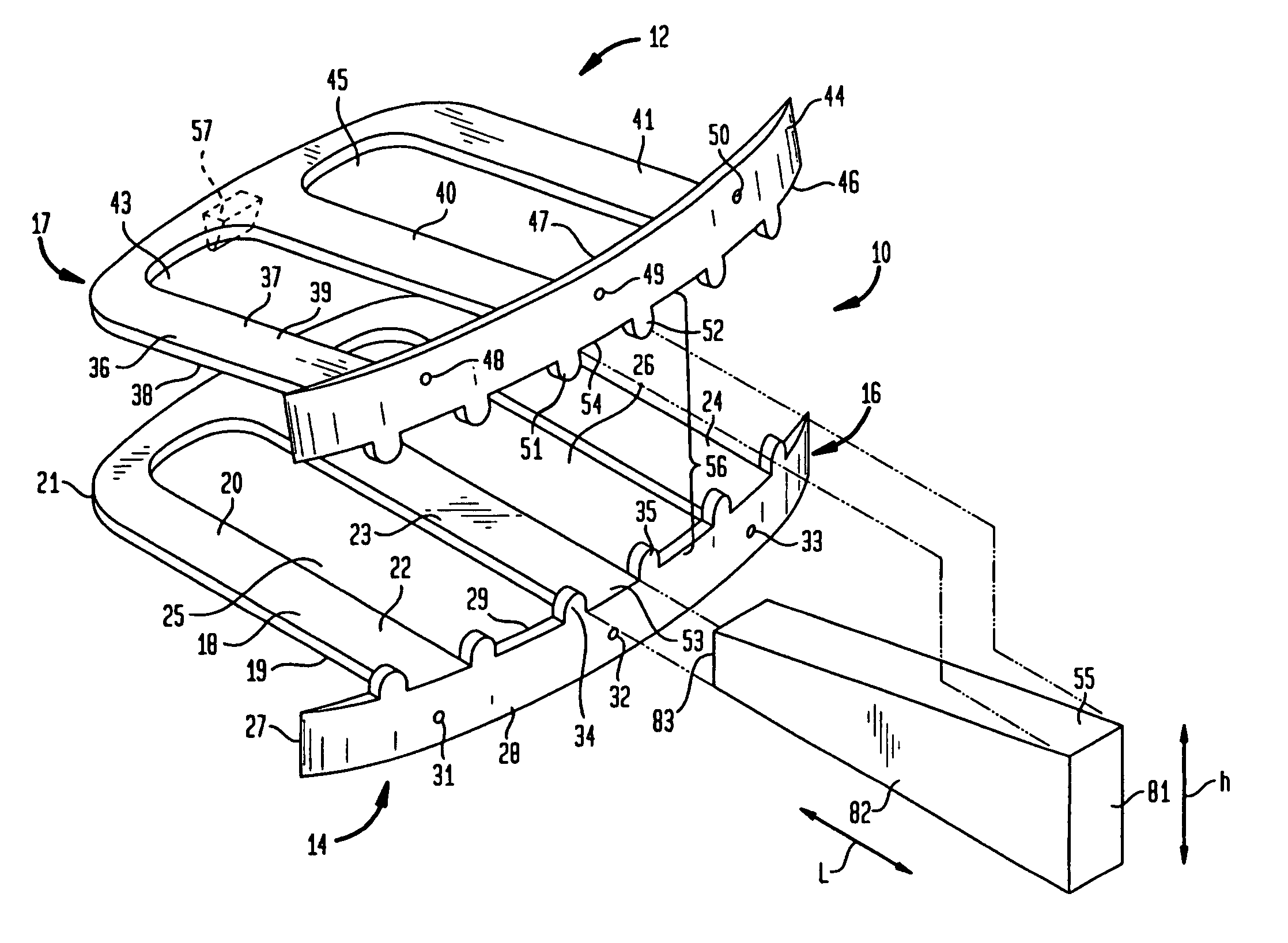
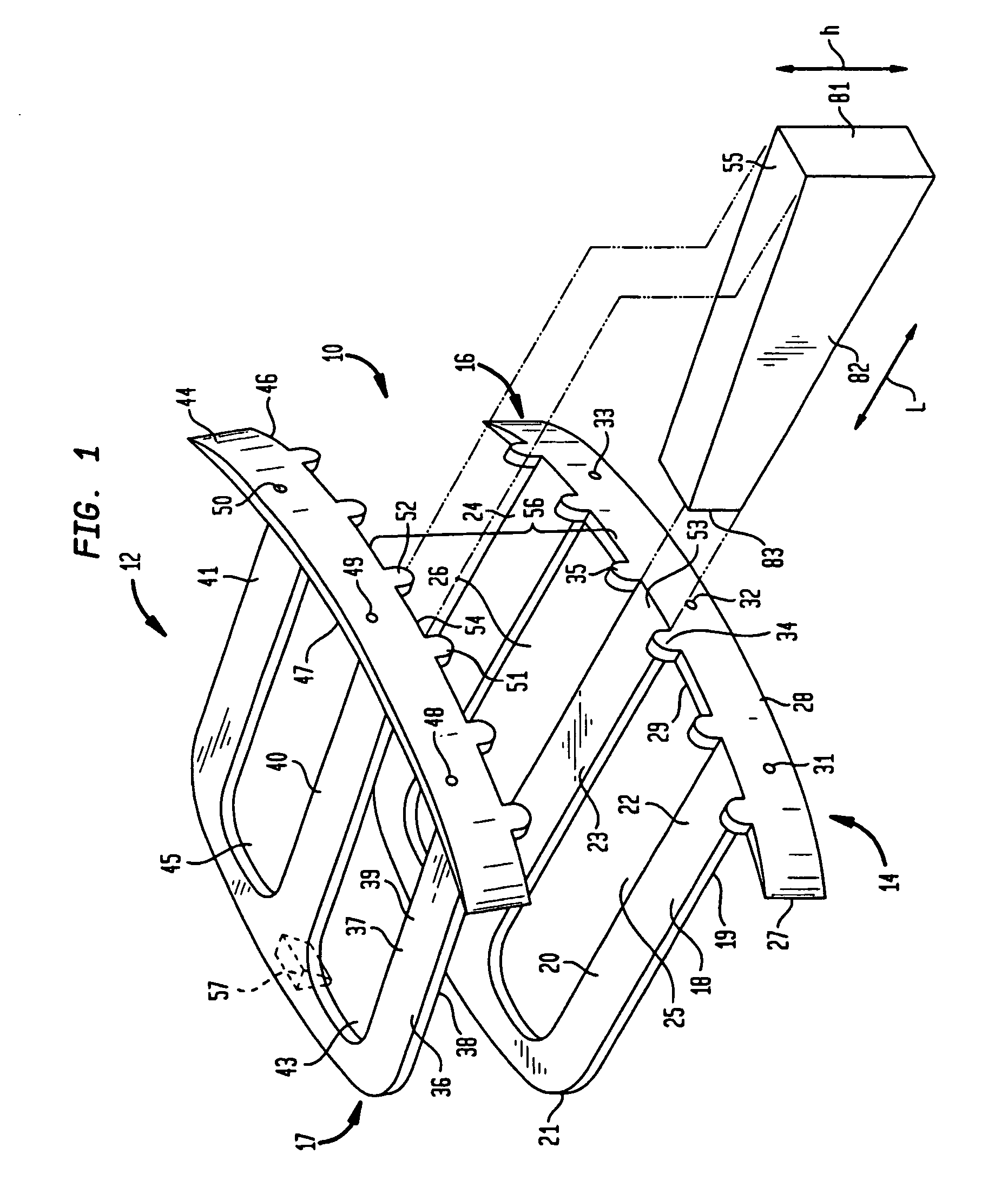
[0027]FIG. 1 is a perspective view of the interbody spinal fusion device 10. Interbody spinal fusion device 10, suitable for implantation in the intervertebral space between two adjacent vertebral bodies (not shown), has a pair of bone-engaging plate members, specifically top plate member 12 and bottom plate member 14. In use, top plate member 12 and bottom plate member 14 are arranged above and below each other, respectively, in spaced apart relationship. The spaced apart relationship is created and maintained in a manner that will be described more completely hereinbelow.

[0028] Bottom plate member 14 has a bottom support plate 18 that is adapted to rest on the endplate of the lower vertebra (not shown). Bottom support plate 18 has an outer surface 19 that contacts the lower vertebra and an inner surface 20. As shown in this figure, bottom support plate 18 is generally flat, but may be adapted to follow the contour of the vertebra on which it rests. Since the support plates merely...


PUM


Abstract

A pair of flat support plates in a spinal fusion implant device contact and rest against the softer, central cancellous bone portion of respective endplates of adjacent vertebrae. Each support plate has a front template that is orthogonal to the plate and is bent to communicate with the anterior surface of the hard cortical endplate the vertebrae. A wedge-shaped support strut in a central channel between the two plates is configured to vary the distance between the support plates such that the height of the device proximate the anterior end is greater than the height of the device at the posterior end to maintain the natural lordosis of the spine. Channels formed on either side of the support strut are filled with bone graft material and contact the endplates of the vertebrae through large openings in the flat support plates to facilitate fusion.

Description

RELATIONSHIP TO OTHER PATENT APPLICATION [0001] This application is a continuation of U.S. Ser. No. 10 / 475,456 filed on Mar. 8, 2004, which is a United States national stage filing under 35 U.S.C. § 371 of international application number PCT / US2002 / 10699 filed on Apr. 4, 2002, and claims the benefit of U.S. Provisional Patent Application No. 60 / 381,579, filed Apr. 4, 2001.BACKGROUND OF THE INVENTION [0002] 1. Field of the Invention [0003] This invention relates generally to a spinal implant system, and more particularly, to an interbody spinal fusion device for promoting the fusion of two adjacent vertebrae. [0004] 2. Description of the Related Art [0005] There is a need in the field of neurosurgery to have spinal implant systems that allow surgeons to increase the probability of successful vertebral fusion procedures. Intervertebral discs that become degenerated due to various factors such as trauma, aging, or disease may be partially or fully removed as a method of pain control. ...

Claims


Application Information

Patent Timeline
Patent Type & Authority Applications(United States)
IPC IPC(8): A61B17/58A61B17/70A61F2/00A61F2/02A61F2/28A61F2/30A61F2/44
CPCA61F2/30744A61F2250/0009A61F2002/2835A61F2002/30517A61F2002/30538A61F2002/30556A61F2002/30604A61F2002/30616A61F2002/30774A61F2002/30779A61F2002/30785A61F2002/30787A61F2002/30975A61F2002/4475A61F2220/0025A61F2250/0006A61F2/4455A61F2002/30593
Inventor RAPP, LAWRENCE G.
Owner RAPP LAWRENCE G
Why Eureka
Try Eureka