

Expandable osteoimplant
a technology of osteoinduction and expandable implants, which is applied in the field of expandable osteoinduction implants, can solve the problems of difficult to achieve uniform endplate preparation, inability to use autografts, and inability to ensure the close contact of osteoconductive and/or osteoinductive materials in the intervertebral space with both vertebral endplates, etc., to achieve greater contact between vertebral endplates and improve the effect of spinal surgery
- Summary
- Abstract
- Description
- Claims
- Application Information
AI Technical Summary
Benefits of technology
Problems solved by technology
Method used
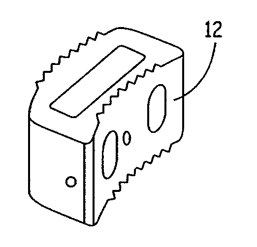
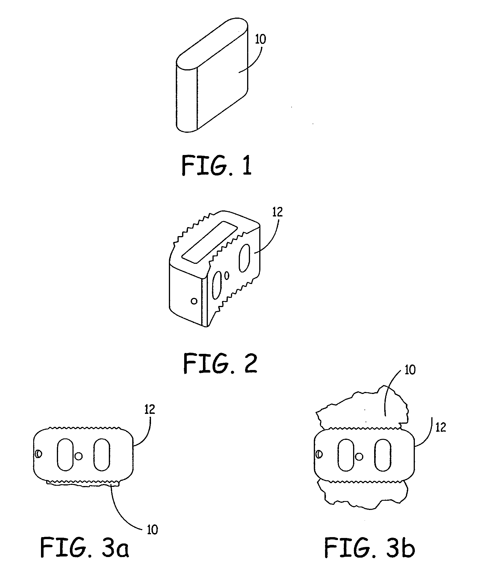
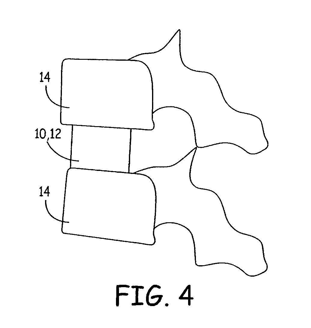
Image

Examples
example 1
[0093] Formation of Osteoimplants:
[0094] 1:1 ratio cancellous chips:cortical fibers
[0095] For a 7 mm implant, inserts were compressed to 4 mm.
[0096] For a 15 mm implant, inserts were compressed to 7 mm.
[0097] Inserts were molded using SLA molds.
[0098] Molds were placed in −70 freezer for one hour, and then freeze dried using a freeze mobile for 24 hours.
[0099] Implants numbered piece 11-piece 16. Pieces 11, 12, and 13 were for a 7 mm implant. Pieces 14, 15, and 16 were for a 15 mm implant.
[0100] Testing:
[0101] After freeze drying, all inserts were weighed and measured using a calibrated digital caliper.
[0102] Measurements were taken at 5 minutes, 60 minutes, and 24 hours while rehydrating. All measurements are in mm.
[0103] Results
[0104]FIG. 8 illustrates an osteoimplant after 0 minutes rehydration. FIG. 9 illustrates an osteoimplant after 30 minutes rehydration.
Piece 11ChipExpan-CountWeightLengthWidthHeightsionPost0.3117.285.396.3lyophilization(0 min.)5 min.10.03.7rehyd...
example 2
[0115] Table I illustrates the results of studies evaluating the expansion characteristics of osteoimplants comprising 100% fibers versus osteoimplants comprising 100% chips. In the osteoimplants comprising 100% cancellous bone chips, the chips ranges in size from 1.7 mm to 10 mm. The test implants were made using 10 mm compression.
TABLE I100% Fibers100% Chips60%60%ChipStartmin.ExpansionExpansionStartmin.ExpansionExpansionCount14.5316.612.0814.314.081514.2516.942.6918.913.7817.934.1531.01714.8616.892.0313.713.8519.315.4639.41714.5516.812.2715.613.9018.624.8134.616.33Avg0.310.180.37Avg0.160.980.931.15DevDev6.998.391.420.06.9915.498.50121.6136.758.601.8527.46.7715.008.23121.6126.938.611.6824.26.8215.398.57125.7136.898.531.6423.86.8615.298.43122.912.67Avg0.120.120.23Avg0.120.260.180.58DevDev
[0116] As may be seen from Table I, the osteoimplants comprising 100% fibers generally expanded about 2 mm. The osteoimplants comprising 100% chips generally expanded about 14 mm. Thus, in these e...
example 3
[0117] Expansion Measurement Techniques and Expansion Data. When used within another implant (such as a vertebral fusion cage), the osteoimplant is confined on its sides by the cage and on its ends by the vertebral end plates. FIG. 13 illustrates sample expansion of an osteoimplant 40 in a vertebral cage 42. As shown, the chips and fibers tend not to extrude out of the cage windows. Equivalent expansion of the implants while they were inserted in cages was measured. The dry dimensions were measured before the implants were put in the cage. During hydration, as the implants expanded, material extended beyond the tops of the cages. Calipers were used to measure the total height of the implants, as they extended beyond both ends of the cages. The difference between the hydrated height and the dry height was the expansion.
[0118] For most runs, the expansion as a function of time was determined by taking measurements at 10 or 15 minute intervals up to one hour. Sometimes additional meas...
PUM
| Property | Measurement | Unit |
|---|---|---|
| size | aaaaa | aaaaa |
| size | aaaaa | aaaaa |
| size | aaaaa | aaaaa |
Abstract
Description
Claims
Application Information