Antenna element and array antenna

Inactive Publication Date: 2006-10-05
SGROV ATLE
View PDF6 Cites 15 Cited by
  • Summary
  • Abstract
  • Description
  • Claims
  • Application Information

AI Technical Summary

Benefits of technology

[0011] An object of the invention is to provide an antenna element which is improved in comparison with previously known solut

Problems solved by technology

The common feature of all these previously known antenna types is that they have frequency-limiting elements which give complex radiation patterns, with a resultant disturbance of the homogeneous field over a considerable frequency range.
There is therefore a need for an antenna structure which also h

Method used


Image

  • Antenna element and array antenna
  • Antenna element and array antenna
  • Antenna element and array antenna

Examples


Embodiment Construction

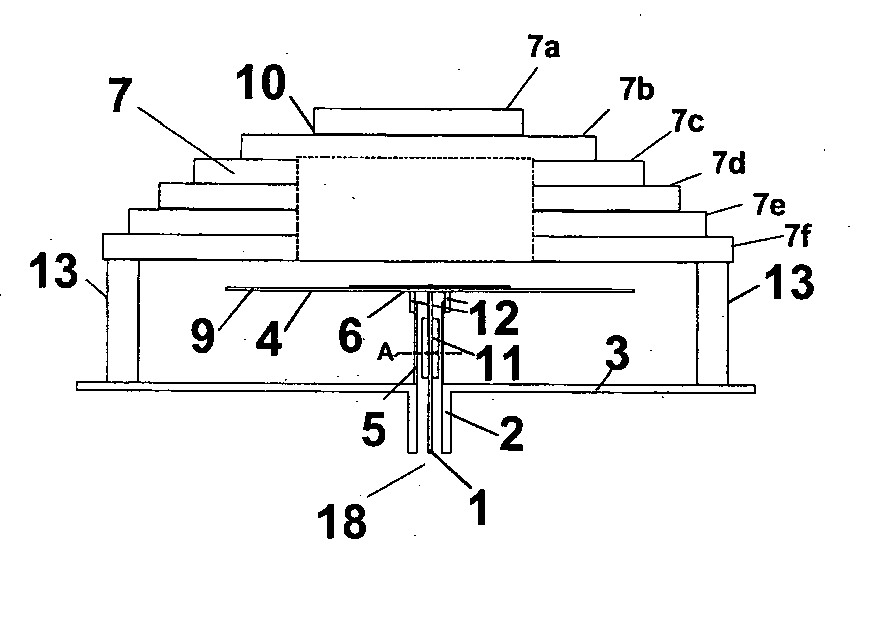
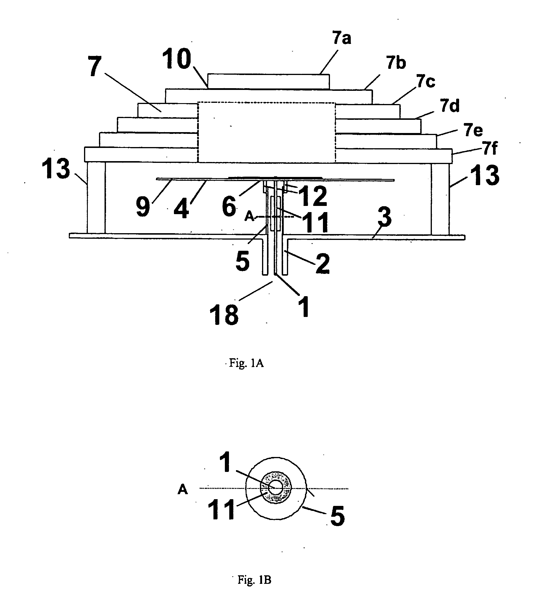
[0032]FIG. 1A is a schematic cross sectional view of the antenna element, viewed from the side. A metallic centre conductor 1 is arranged to pass a signal from a connection point 18 to an excitation element 6. The centre conductor 1 extends in an axially centred manner through a cylindrical transmission line jacket 2 and through an aperture in a ground plane 3. The centre conductor 1 extends further in an axially centred manner through a cylindrical excitation sleeve 5. The section of the centre conductor 1 that extends through the excitation sleeve5 advantageously comprises an impedance matching element 11 for matching the high impedance in the antenna to a standard 50Ω system which will be connected to the connection point 18. The impedance matching element 11 may be implemented as a cylinder of a dielectric with a high dielectric constant, which encloses the centre conductor 1, and which is further enclosed by the excitation sleeve. Alternatively, the impedance matching may be im...


PUM


Abstract

An antenna element for an array antenna comprises a transmission line (1) passed through a ground plane (3), connected at an excitation point (8) to a flat, conductive, helical excitation element (6) mounted on a dielectric substrate (4) on the top of and parallel to the ground plane (3). The distance between the excitation element (6) and the ground plane (3) is greater than one eight of the longest wavelength of the signals with which the antenna is arranged to operate, and preferably between 0.25 and 0.50 times the wavelength. The path length of the electric conductor that constitutes the excitation element is greater than the said wavelength, and preferably between 10 and 100 times the wavelength. This causes the excitation element to operate as a leakage wave structure, with the result that the antenna element becomes non-resonant. An array antenna is further described with a number of such antenna elements arranged in a square matrix configuration, where a common ground plane (3) and a common substrate (4) are employed. A dielectric lens (7) is mounted on the top of the antenna element or the array antenna.

Description

TECHNICAL FIELD [0001] The invention relates to an antenna element, particularly an antenna element for use in electrically controlled array antennas employed in the field of location determination or optimisation of traffic capacity in wireless communication systems. The invention also relates to an array antenna in which the antenna element is incorporated, together with an application of the array antenna. BACKGROUND OF THE INVENTION [0002] In wireless communication systems there are some situations where there is a need to locate the mobile and stationary communication units with great accuracy. There is also a need for more intelligent use of the physical layer in the communication model in order to increase the capacity and availability in the available frequency bands where the density of users is high. [0003] In this connection an apparatus has previously been developed for location determination, described in international patent application WO-01 / 30099, belonging to the ap...

Claims


Application Information

Patent Timeline
IPC IPC(8): H01Q1/38H01Q1/36H01Q9/04H01Q9/27H01Q19/06
CPCH01Q9/0407H01Q19/062H01Q9/27
Inventor SAEGROV, ATLE
Owner SGROV ATLE
Why Eureka
Try Eureka