Initial acceleration circuit for dias circuit proportional to absolute temp

A bias circuit, absolute temperature technology, applied in the direction of adjusting electrical variables, control/regulation systems, instruments, etc.

Active Publication Date: 2006-01-25
ETRON TECH INC
View PDF16 Cites 17 Cited by
  • Summary
  • Abstract
  • Description
  • Claims
  • Application Information

AI Technical Summary

Problems solved by technology

Referring to Fig. 5, when the energy bandgap reference voltage source circuit 5 is providing the energy bandgap refer

Method used


Image

  • Initial acceleration circuit for dias circuit proportional to absolute temp
  • Initial acceleration circuit for dias circuit proportional to absolute temp
  • Initial acceleration circuit for dias circuit proportional to absolute temp

Examples


Embodiment Construction

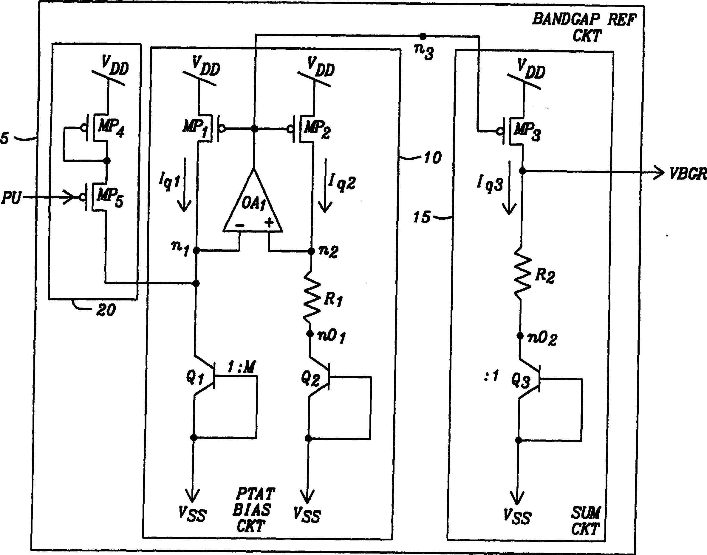
[0071] The speed-up circuit of the present invention is used to initialize a PTAT bias circuit. When the PTAT bias circuit is activated, the acceleration circuit detects the activation and cuts it off. A power-on signal is applied to the speed-up circuit to provide an indication that a supply voltage source has reached a threshold level. A feedback signal is then received through the speed-up circuit indicating that the PTAT bias circuit has left its degraded operating point. When the feedback signal indicates that the degraded operating point is left, the acceleration circuit is automatically disabled.

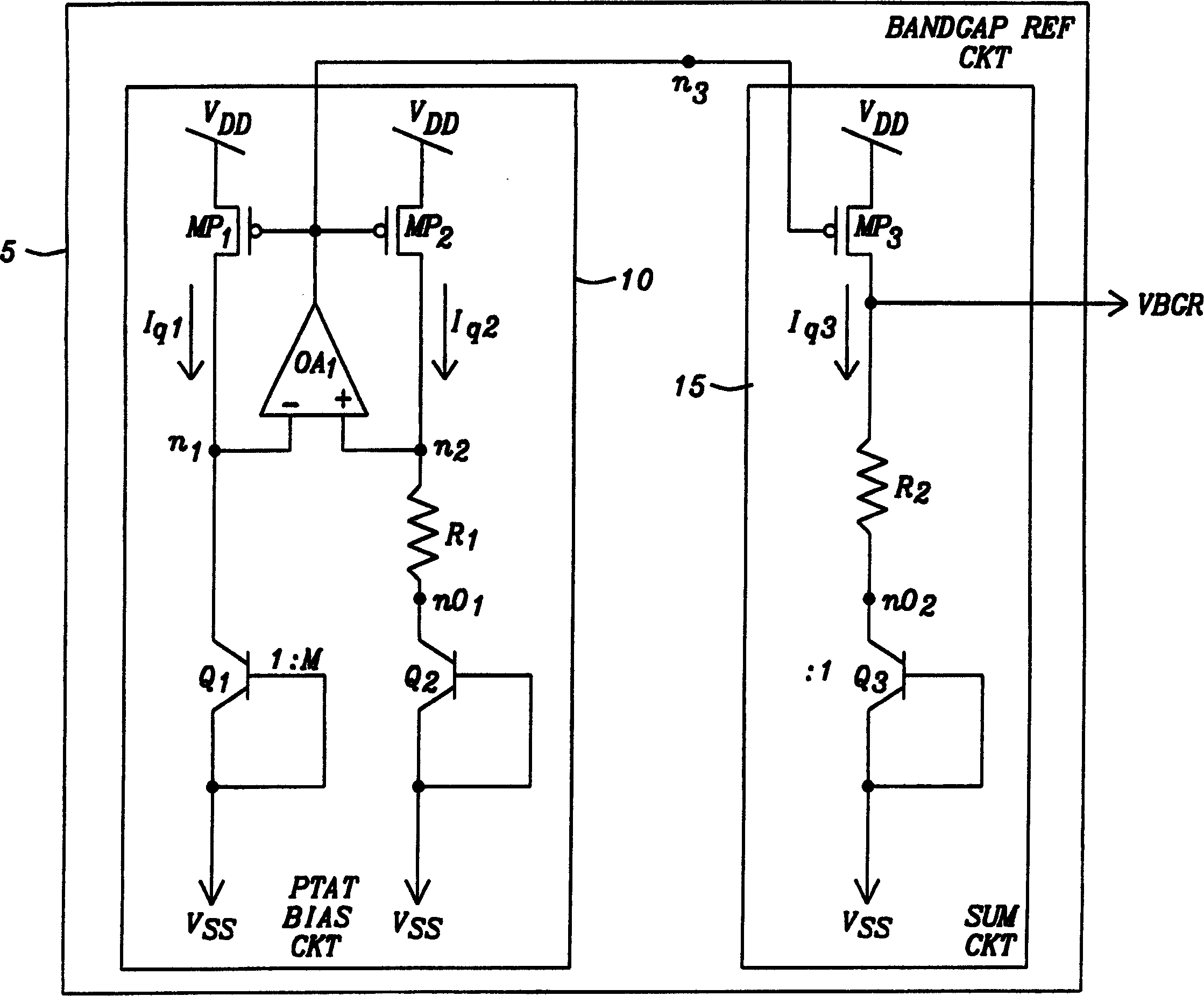
[0072] refer to Figure 6a A bandgap reference voltage source 105 is depicted. The PTAT bias circuit 110 is constructed and used as figure 1 The PTAT bias circuit 10 in is operated. The acceleration circuit 120 of the present invention is connected to receive the power supply voltage source V DD The power-on signal PU of the operating state. When the power-up signal PU...


PUM


Abstract

A PTAT biasing circuit for use in a bandgap referenced voltage source includes a startup sub-circuit. Prior to activation of a power up indication signal, the speedup circuit forces the PTAT biasing circuit from a degenerate operating point to a normal operating point. Upon detection of a feedback signal denoting the initiation of the PTAT biasing circuit, the startup sub-circuit terminates operation of the startup sub-circuit independent of the activation of the power up indication signal.

Description

technical field [0001] The invention relates to a reference bias circuit, in particular to a PTAT (proportional to absolute temperature) bias circuit and a bandgap voltage reference circuit incorporating a PTAT bias circuit. More particularly, the present invention relates to start-up circuits for PTAT (Proportional to Absolute Temperature) bias circuits. Background technique [0002] Bandgap reference voltage source circuits are well known in the art, and these circuits provide a voltage standard independent of temperature variations in the circuit. [0003] The reference voltage of the bandgap reference voltage source is the voltage V developed between the base and emitter of a bicarrier junction transistor (bicarrier transistor) be and the base-emitter voltage V of the other two bipolar transistors be Difference (ΔV be )The function. The base-emitter voltage V of the first bipolar transistor be has a negative temperature coefficient, or the base-emitter voltage V be...

Claims


Application Information

Patent Timeline
IPC IPC(8): G05F1/567G05F3/26
CPCG05F3/30
Inventor 许人寿
Owner ETRON TECH INC
Why Eureka
Try Eureka