Electronic lock with flywheel self-powering apparatus

A self-generating and electronic lock technology, applied in the field of electronic locks, can solve the problems of unfavorable popularization and application of electronic locks at home, troublesome use, etc.

Inactive Publication Date: 2006-02-08
东莞市摩德隆智能科技有限公司
View PDF0 Cites 19 Cited by
  • Summary
  • Abstract
  • Description
  • Claims
  • Application Information

AI Technical Summary

Problems solved by technology

However, because the current electronic lock structure must be driven by batteries, once the battery is dead, the lock cannot be opened. At this time, another set of auxiliary mechanical lock structure must be used to open the lock, which is troublesome to use and is not conducive to electronic locks. household popularization and promotion and application in various fields

Method used


Image

  • Electronic lock with flywheel self-powering apparatus
  • Electronic lock with flywheel self-powering apparatus
  • Electronic lock with flywheel self-powering apparatus

Examples


Embodiment Construction

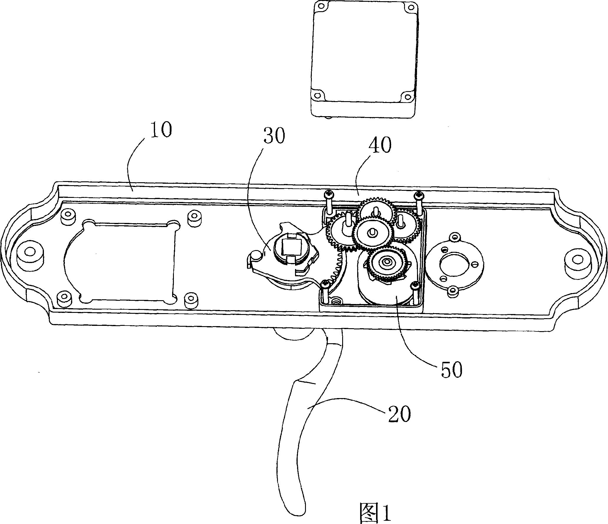
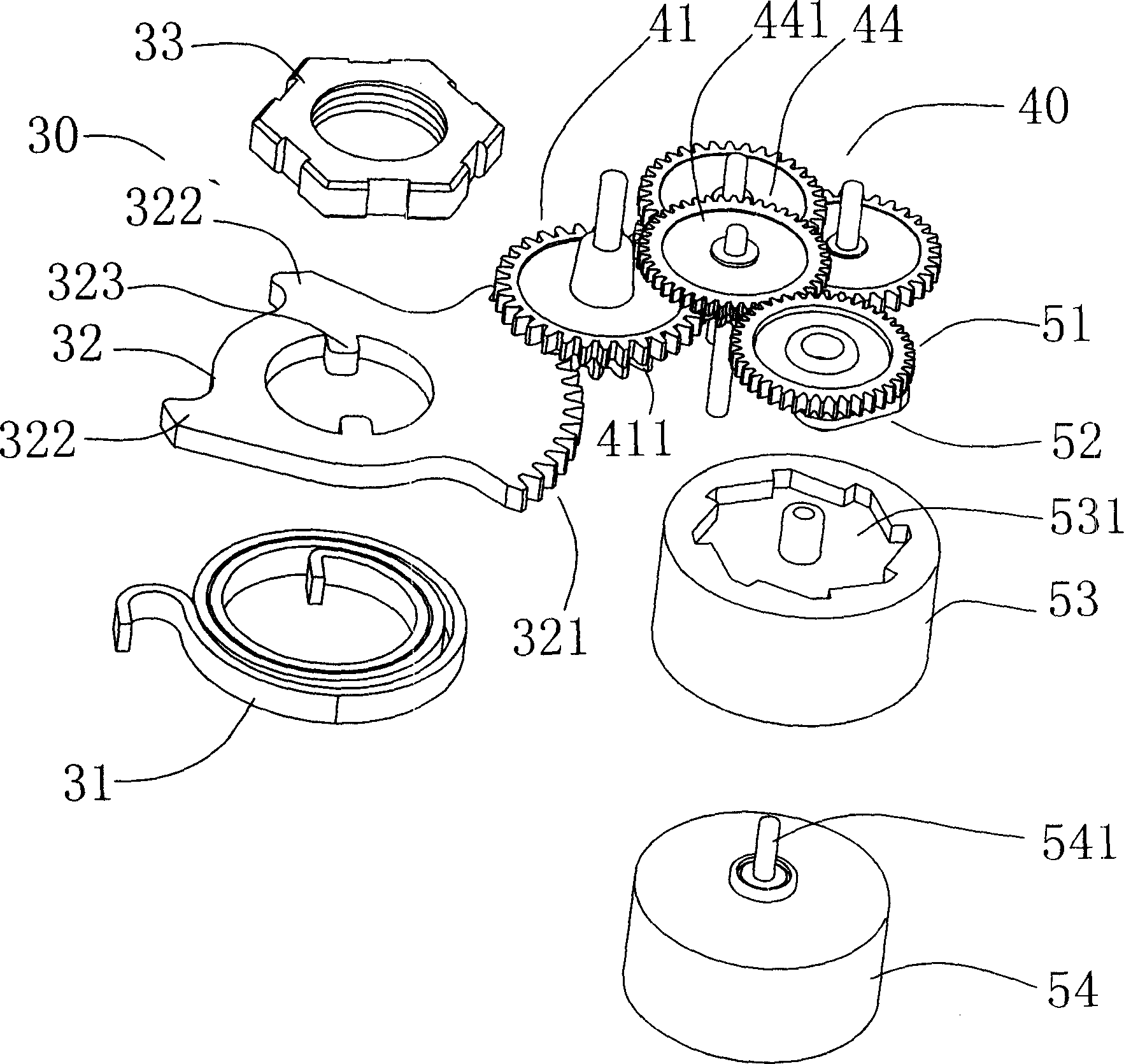
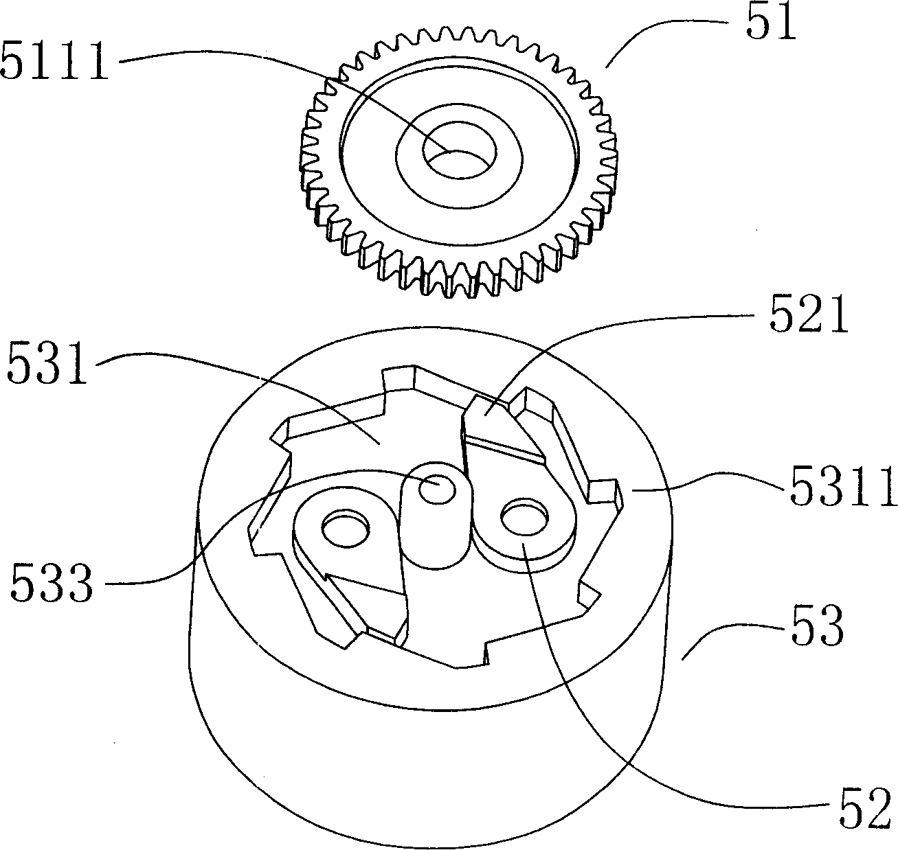
[0012] As attached picture 1~ Figure 5 As shown, the present invention includes a lock frame plate 10 and a lock cylinder, and a handle 20 is installed on the outer surface of the lock frame plate 10, and one end of the handle 20 is connected with the handle shaft device 30 in the lock frame plate 10, and the handle shaft device 30 includes an elastic element 31 that can reset the handle and a rotating plate 32 with an arc-shaped rack 321 formed on the edge. The arc-shaped rack 321 of the rotating plate 32 meshes with the input gear 411 of the transmission gear set 40, and the lock frame plate 10 It also includes a flywheel self-generating device 50, which consists of a driving gear 51, a diamond-shaped plate 511 formed in the center of the bottom surface of the driving gear 51, and two rotating arms 52 symmetrically sleeved on fixed shafts 512 at both ends of the surface of the diamond-shaped rotating plate 511. , a flywheel 53 and a micro-generator 54, the output gear 442 o...


PUM


Abstract

The present invention relates to lock technology, and is especially one kind of electronic lock with flywheel generator. The electronic lock includes lock frame and lock core, and has one handle mounted onto the outer surface of the lock frame, one rotation shaft unit with elastic element to reposition the handle and toothed turntable meshed with the input gear of the transmission gear set, one flywheel generator comprising driving gear, diamond plate, rotation arms symmetrically on the fixed shaft, flywheel and miniature generator, and one transmission gear set with output gear meshed to the driving gear. The present invention makes it possible for the electronic lock not to depend on battery.

Description

technical field [0001] The invention relates to the technical field of locks, in particular to an electronic lock which utilizes a flywheel self-generating device without a power supply. Background technique [0002] With the development of the lock industry, various electronic locks emerge in an endless stream. Because electronic locks are more convenient to use, they are widely used in various fields. However, because the current electronic lock structure must be driven by batteries, once the battery is dead, the lock cannot be opened. At this time, another set of auxiliary mechanical lock structure must be used to open the lock, which is troublesome to use and is not conducive to electronic locks. household popularization and promotion and application in various fields. How to conveniently solve the power supply problem of electronic locks has become a difficult problem to be solved in the popularization and application of electronic locks. Contents of the invention ...

Claims


Application Information

Patent Timeline
Patent Type & Authority Applications(China)
IPC IPC(8): E05B47/00H02K7/00
Inventor 吴斐
Owner 东莞市摩德隆智能科技有限公司
Why Eureka
Try Eureka