Steel bar bounding, clamping and forming method and device thereof

A technology of clamping position and bar, applied in the parts, packaging and other directions of strapping machinery, which can solve the problems of large machine, complex device structure and low efficiency.

Inactive Publication Date: 2006-02-15
耿宝峰
View PDF8 Cites 17 Cited by
  • Summary
  • Abstract
  • Description
  • Claims
  • Application Information

AI Technical Summary

Problems solved by technology

There is also a forming method, they are not formed by clamping but stacked layer by layer in a hexagonal mold, such as US patents 4,120,406, 4,174,662, 5,387,072, but such devices have complex structures, huge machines, and low efficiency. Low

Method used


Image

  • Steel bar bounding, clamping and forming method and device thereof
  • Steel bar bounding, clamping and forming method and device thereof
  • Steel bar bounding, clamping and forming method and device thereof

Examples


Embodiment Construction

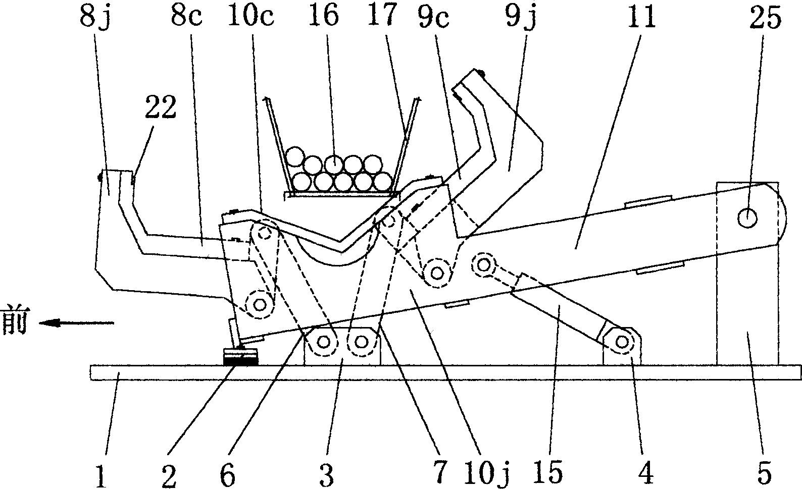
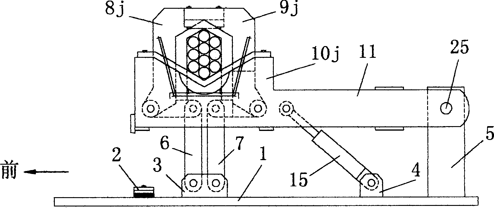
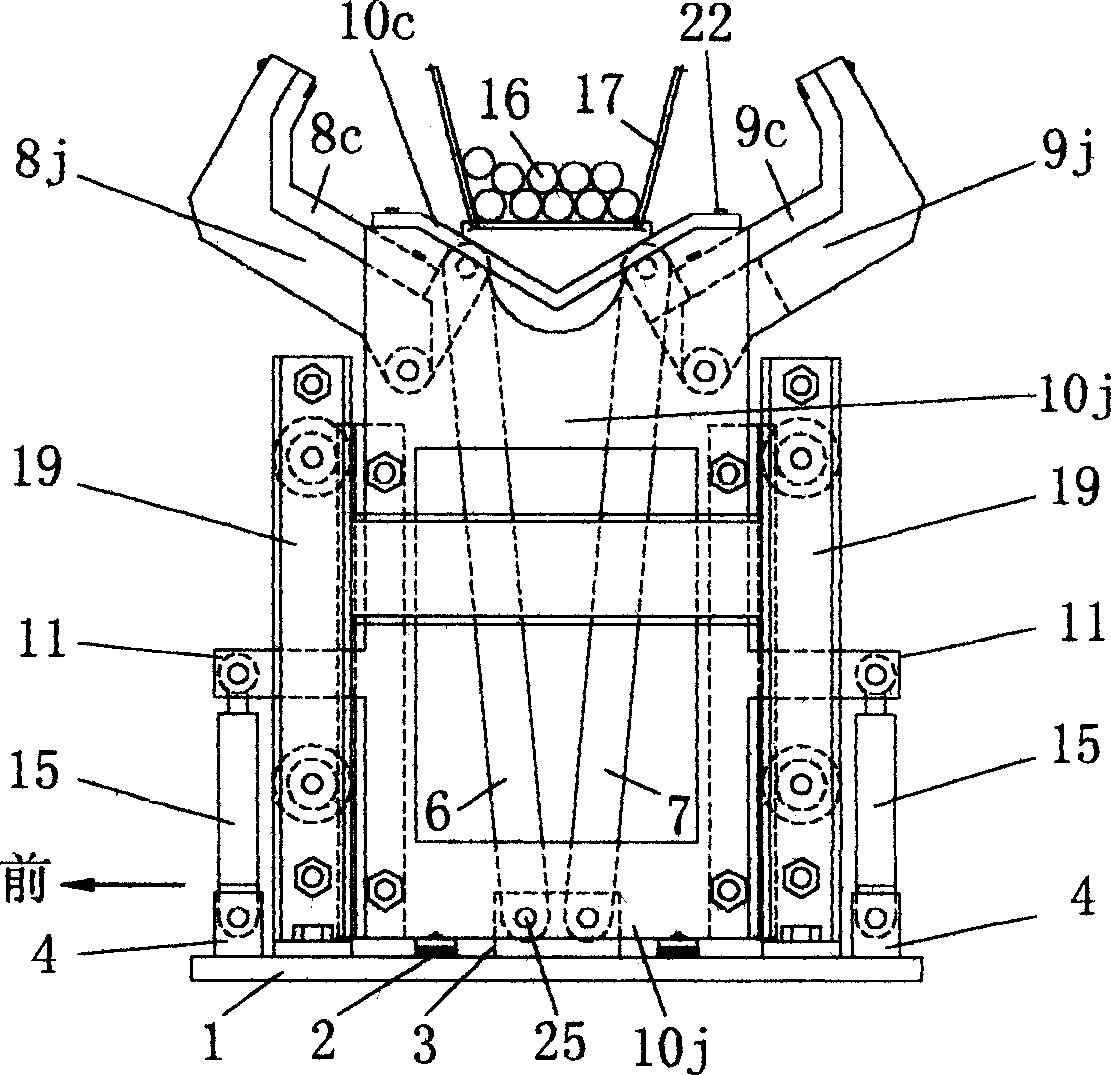
[0047] A method for forming bars by bundling and clamping them. refer to Figure 19 , including three rigid claws with front claws, rear claws, and supporting claws to clamp and form the bar group. The process of clamping and forming is divided into two steps:

[0048] The first step is to use the supporting claws 10 extending with guide slopes on both sides of the bundle-shaped part to hold up the rods 16 that are placed on the bottom of the rod conveying groove 17 and prepare to be bundled, so that the rods 16 on both sides of the bundle-shaped position are in the On the guide slope, the adjacent rods 16 are in mutually undulating and staggered positions in the direction in which the front paws 8 and the rear paws 9 move toward each other.

[0049] The second step is that the opposite-moving front claws 8 and rear claws 9 start to squeeze the rods 16 on the guide slope, so that the undulating and staggered rods 16 squeeze into the upper space through the sliding of the surf...


PUM


Abstract

This invention provides a method and device to clamp and shape the metallurgical bar material before baling; wherein, the method comprises two steps: first, holding up the material on conveying trough bottom to make material on sides of baling form place lay on guide slope, arranging the near material on interlaced place along the opposite movement direction of front and back jaws; second, the front and back jaws extrude the bar material toward upper space till clamp and shape. The jaw of this device can be integrated or combined type, wherein the latter can clamp small and large size bar materials into circular and hexagon separately. The invention has special form process with wide size and long service life.

Description

technical field [0001] The invention relates to a method and device for forming metallurgical bars before bundling. Background technique [0002] For small-sized bars, the bars are generally bundled into round bundles and clamped to form them. There are two kinds of existing clamping and forming devices. One is flexible, the inner sides of two parabolic or curved steel plates are respectively fixed on chains, so that the two chains move face to face, and the two chains are used to tighten the bar, but because the bar is placed flat on the bar The bottom of the material conveying groove, so the bars of the same specification are also arranged layer by layer based on the bottom. When the two chains move face to face, the adjacent bars in the horizontal direction play a role. The role of mutual support, at this time, the flexible chain will touch the upper bar, coupled with the self-weight and friction of the bar, it is difficult for the bar to move upward, and the section of...

Claims


Application Information

Patent Timeline
Patent Type & Authority Applications(China)
IPC IPC(8): B65B13/18B65B63/00B65B27/10
Inventor 耿宝峰
Owner 耿宝峰
Why Eureka
Try Eureka