Calibrating method for scanning instrument
A calibration method and scanner technology, applied in the field of scanner calibration, can solve problems such as application limitations, achieve the effect of high repetition rate and reduce linearity error
- Summary
- Abstract
- Description
- Claims
- Application Information
AI Technical Summary
Problems solved by technology
Method used
Image
Examples
Embodiment 1
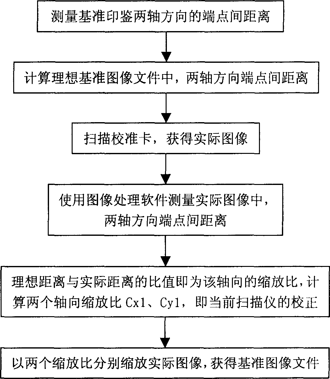
[0033] The flow of this embodiment is as follows figure 2 shown.
[0034] 1) Making benchmark stamps and measuring: Use metals with low deformation at room temperature. In this embodiment, a copper material is used to make a perfect circular stamp. The imprinted surface of the stamp is a combination of patterns and characters, and its edges are smooth and tidy. There is an endpoint at both ends of the x and y axes of the stamp. Use a measuring microscope to measure the distance between the two axes of the seal.
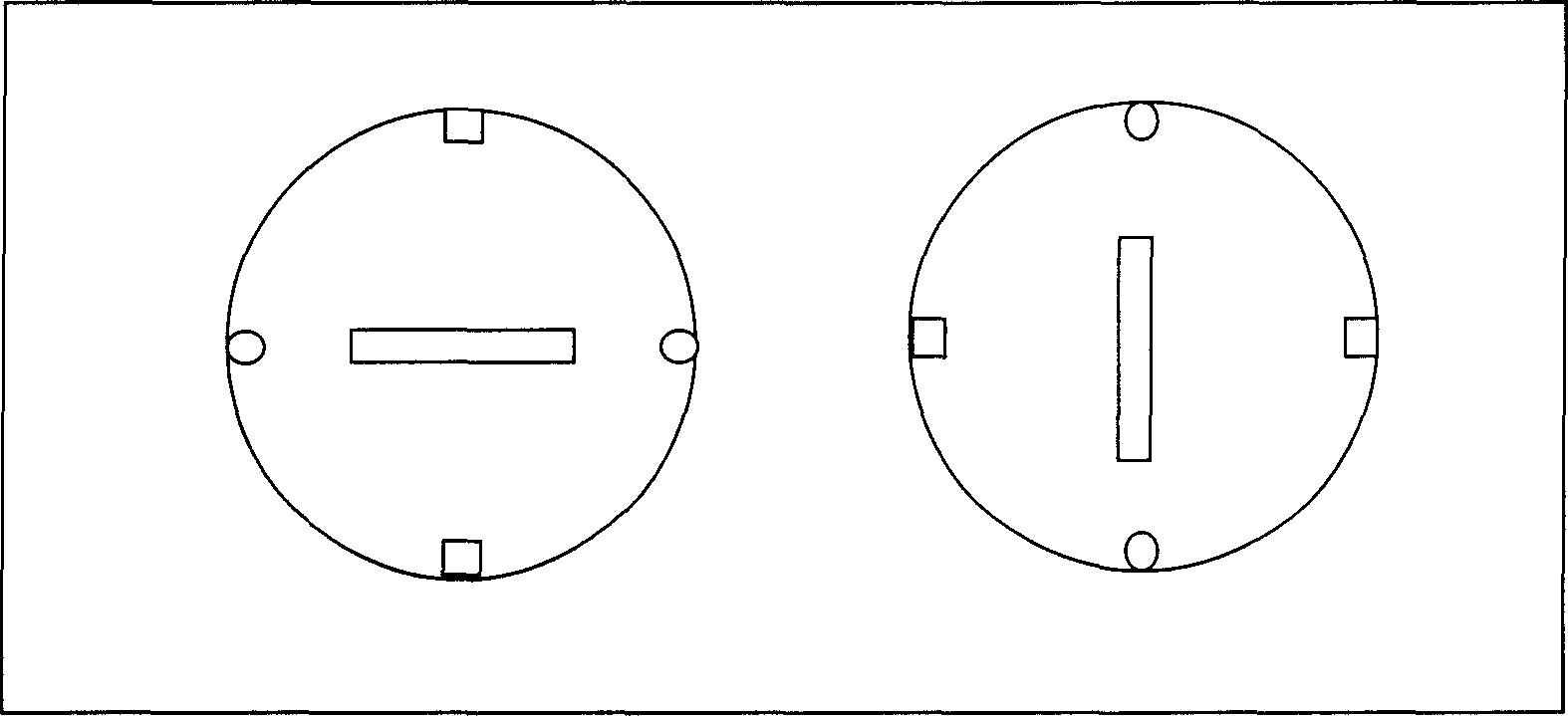
[0035] 2) Make a scanner calibration card: choose a relatively solid paper, and print two seals with the reference seal. The angle difference between the two prints is 90°, and the distance between the two prints is about 20mm, such as figure 1 shown. Cut the paper to a size of 200×100mm.
[0036] 3) Obtaining the reference image file: the reference image file is the theoretical image data corresponding to the printed text of the calibration card (or the referenc...
Embodiment 2
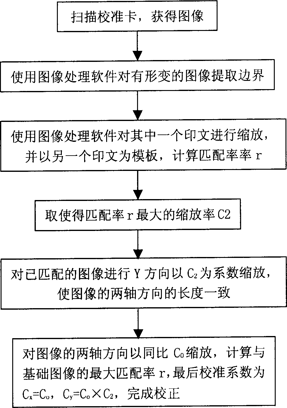
[0045] The flow of this embodiment is as follows image 3 shown.
[0046] 1) Making a reference seal and measuring: In this embodiment, copper material is used to make a square seal. The seal surface is a combination of patterns and characters, and its edges are smooth and tidy; the x and y axes of the seal each have an endpoint . Use a measuring microscope to measure the distance between the two axes of the seal.
[0047] 2) Obtain the calibration card and reference image file as in embodiment 1, the effect of the reference image file is as follows Figure 5 .
[0048] 3) Use a scanner to scan the calibration card to obtain a preliminary image. After extracting the image, use one of the printed images as the template image IMG_M, rotate and scale the other image IMG_T to match the template image IMG_M, and calculate the matching rate. In this embodiment, the formula for calculating the matching rate is: r = ( N ...
Embodiment 3
[0051] The flow of this embodiment is as follows image 3 shown.
[0052] 1) Obtain reference stamp, calibration card and reference image file as in Example 1.
[0053] 2) Use a scanner to scan the calibration card to obtain a preliminary image. After extracting the image, use one of the printed images as the template image IMG_M, rotate and scale the other image IMG_T to match the template image IMG_M, and calculate the matching rate. In this embodiment, the formula for calculating the matching rate is: r = I ∩ M I ∪ M = Σ i = 1 n I i ∩ M i ...
PUM
 Abstract
Description
Claims
Application Information
 - R&D
- Intellectual Property
- Life Sciences
- Materials
- Tech Scout
- Unparalleled Data Quality
- Higher Quality Content
- 60% Fewer Hallucinations
Browse by: Latest US Patents, China's latest patents, Technical Efficacy Thesaurus, Application Domain, Technology Topic, Popular Technical Reports.
© 2025 PatSnap. All rights reserved.Legal|Privacy policy|Modern Slavery Act Transparency Statement|Sitemap|About US| Contact US: help@patsnap.com


