
Information recording method, information recording device, and recording medium containing a program

A technology for information recording and recording media, which is applied in the field of information recording, information recording devices and recording media for recording programs, and can solve problems such as data errors, jitter deterioration, mark shape and mark position accuracy damage, etc.

Inactive Publication Date: 2006-03-08
RICOH KK
View PDF0 Cites 3 Cited by
  • Summary
  • Abstract
  • Description
  • Claims
  • Application Information

AI Technical Summary

Problems solved by technology

[0010] However, in such an OPC method, since the relationship between the recording power and the deviation from the ideal value of each of the data lengths is determined by the rapid cooling (rapid cooling) conditions by the arrangement of the heating pulse and the cooling pulse, according to the even length and the count The data length of the length varies from group to group, so different optimal recording powers are calculated from the combination of the preset pulse width and pulse edge position in the low-level format (pre-format) information of the disc and the preset recording power. In the case of the mark length and the deviation from the ideal value increases
More specifically, in the case of recording medium and recording device deviation (that is, deviation of the recording pulse waveform caused by the deviation of the LD driver), the optimum recording power Po (optimum) and the pulse of the recording pulse The relationship between the width and the optimum value of the pulse edge position also deviates, so the accuracy of the mark shape and mark position is deteriorated, and the jitter characteristics are deteriorated, resulting in problems that cause data errors

Method used


Image

  • Information recording method, information recording device, and recording medium containing a program
  • Information recording method, information recording device, and recording medium containing a program
  • Information recording method, information recording device, and recording medium containing a program

Examples


Embodiment Construction

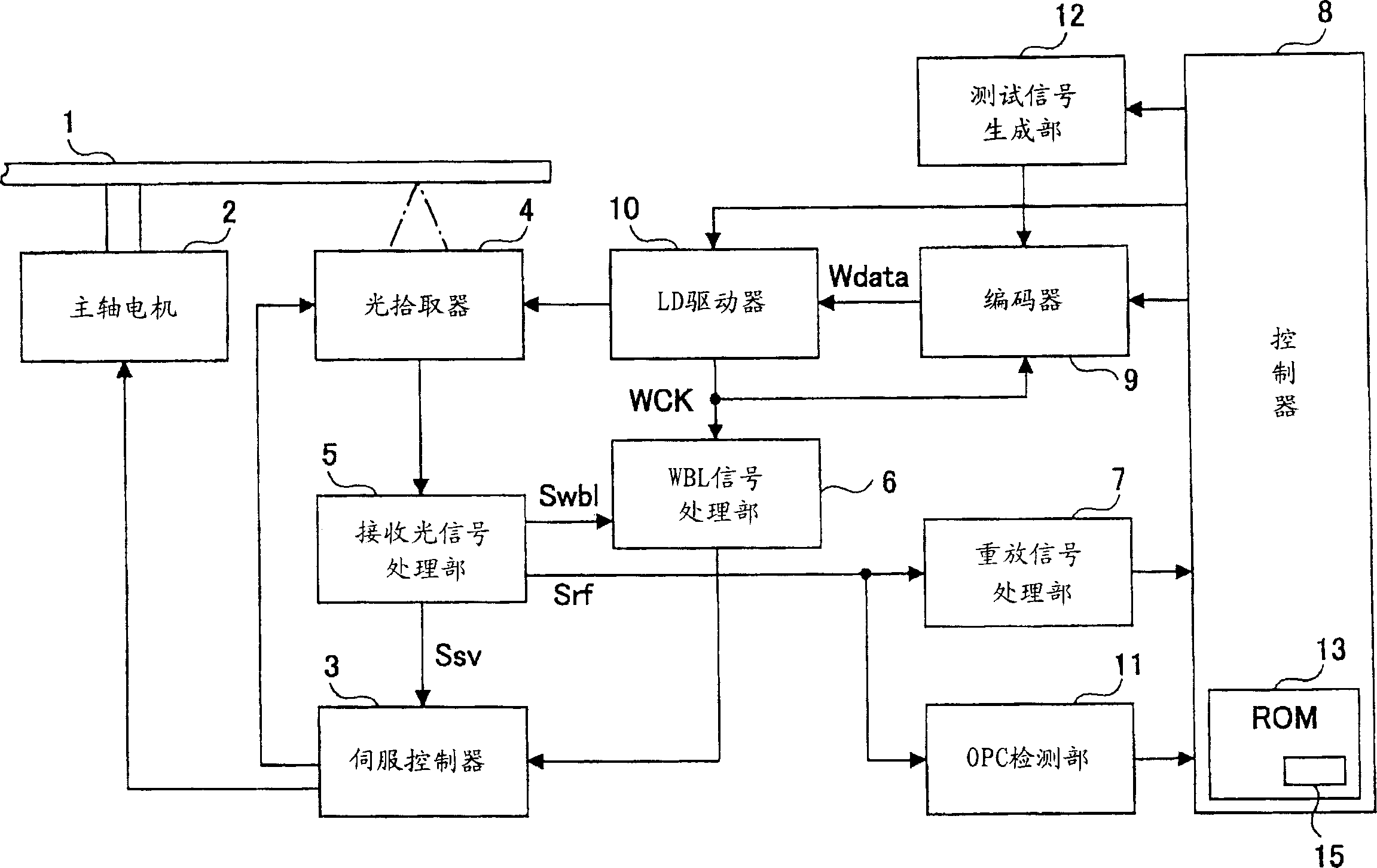
[0058] One embodiment of the present invention will be described based on the drawings. The information recording device of this embodiment is an application example to an optical information recording device, Figure 1A is a block diagram showing a schematic configuration example of the optical information recording device.

[0059] The recording medium 1 used in this optical information recording apparatus is a recordable recording medium (for example, CD-R, CD-RW, DVD-R, DVD-RW, DVD+R, DVD+RW, DVD-RAM, MD , MO and other discs, etc.). The spindle motor 2 that rotationally drives such a recording medium 1 is controlled so as to have a constant linear velocity (CLV) or a constant angular velocity (CAV) based on a signal supplied from a servo controller 3 . The optical pickup (PU) 4 is used to irradiate the outgoing light from the semiconductor laser (LD) as the light source onto the recording medium 1 and record information, or receive the reflected light from the recording ...


PUM


Abstract

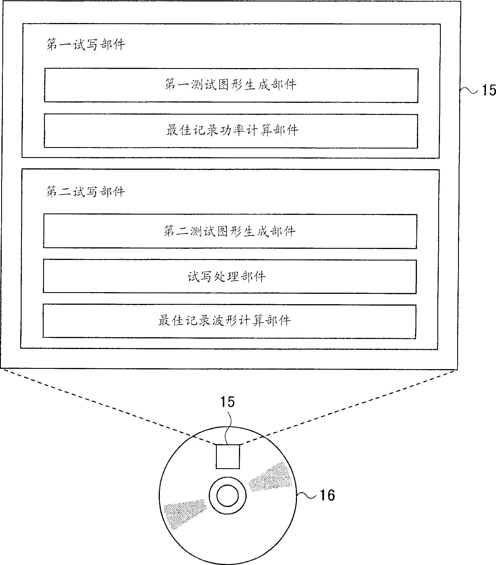
[Problem to be Solved] Accurate recording is achieved by obtaining each optimum pulse width and pulse edge position in a recording method that performs recording according to the rules of recording waveform using different pulse widths and pulse edge positions for individual data length sets with respect to the data length sets having the different relationship between the number of pulses and the data length. [Means for Solving the Problem] The first trial write process obtains an optimum recording power of a test pattern (S1 through S3) even with respect to data having different rules for the recording waveforms corresponding n type data length sets, and the second trial write process using this optimum recording power obtains optimum pulse width or optimum pulse edge position separately for each data length set (S4 through S6). Based on the optimum recording power and optimum recording waveform obtained by these trial write processes, recording operation is performed so as to form all the data lengths with satisfactory accuracy, thereby making it possible to obtain a proper reproduced signal.

Description

technical field [0001] The present invention relates to an information recording method for various recording media such as CD-R, CD-RW, DVD-R, DVD-RW, DVD-RAM, and DVD+RW, an information recording device, and a recording medium for recording a program. Background technique [0002] In recent years, for example, recordable optical disk drives such as CD-R drives have been put into practical use, and studies aimed at increasing the capacity and recording at a higher speed have been conducted. Examples of recordable optical disc media include write-once optical discs using dye-based media, etc., rewritable discs using magneto-optical media, phase change media, and the like. [0003] In a general optical disk recording device, a semiconductor laser is used as a light source, and the laser light pulse-modulated according to recording information is irradiated onto a recording medium to form a recording mark. At this time, since the power of the laser light for recording changes...

Claims


Application Information

Patent Timeline
Patent Type & Authority Applications(China)
IPC IPC(8): G11B7/0045G11B7/125G11B7/1267
CPCG11B7/1267G11B7/00736G11B7/0062
Inventor 横井研哉增井成博
Owner RICOH KK
Learn More