Check patentability & draft patents in minutes with Patsnap Eureka AI!

Communication terminal device and radio communication method

A radio communication and communication terminal technology, applied in the field of communication terminal equipment, can solve problems such as increased uplink interference, increased power consumption of communication terminal equipment, and decreased system capacity

Inactive Publication Date: 2006-03-08
PANASONIC CORP
View PDF1 Cites 7 Cited by
  • Summary
  • Abstract
  • Description
  • Claims
  • Application Information

AI Technical Summary

Problems solved by technology

[0013] However, causing the communication terminal equipment to generate and transmit a new signal to report the packet transmission method will result in increased interference in the uplink, decreased system capacity, and increased power consumption of the communication terminal equipment

Method used


Image

  • Communication terminal device and radio communication method
  • Communication terminal device and radio communication method
  • Communication terminal device and radio communication method

Examples


Embodiment 1

[0025] Embodiment 1 describes a mode in which when a communication terminal device transmits packet data using predetermined transmission parameters without scheduling by a base station device (second packet transmission method), information requesting scheduling (hereinafter referred to as "SRQ information") will be will not be sent to the base station equipment. The SRQ information is information indicating the amount of data requested by the communication terminal device, the transmission rate, or the available transmission power.

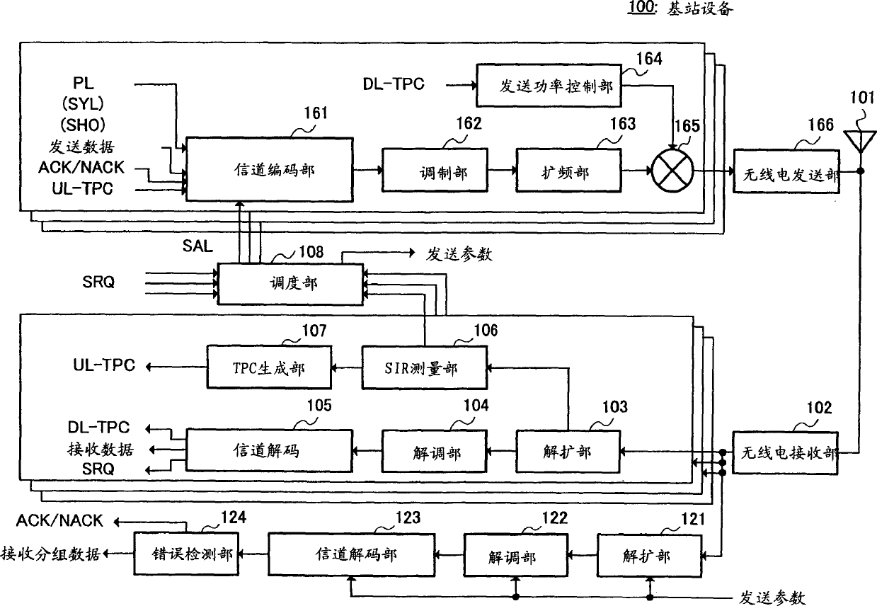
[0026] First, the operation of each component of the base station apparatus 100 according to the present embodiment will be described using the block diagram in FIG. 1 .

[0027] The radio reception section (RE-RF) 102 converts the radio reception signal received by the antenna 101 into a baseband digital signal, and outputs the signal to the despreading section (DES) 103 and the despreading section (DES) 121 .

[0028] The number of despreadin...

Embodiment 2

[0078] Embodiment 2 describes a mode in which, when a communication terminal device transmits packet data using a predetermined transmission parameter without scheduling by a base station device (second packet transmission method), a specific value that transmission of packet data is never permitted is transmitted SRQ information.

[0079] In Embodiment 2, the structure of the base station equipment and the structure of the communication terminal equipment are completely the same as those shown in FIG. 1 and FIG. operation is different.

[0080] The SRQ information generation section 224 of the present embodiment holds a table indicating the relationship among the amount of data in the buffer 242 , available transmission power, and SRQ information, as shown in FIG. 6 . Available transmission power is expressed in decibels (dB) as a ratio to the value calculated by the transmission power calculation section 222 .

[0081] When the first packet transmission method is selected,...


PUM


Abstract

A transmission method selection section (223) selects a first packet transmission method or a second packet transmission method. When the first packet transmission method is selected, an SRQ information generation section (224) generates an SRQ (scheduling request) according to the data amount measured by a data amount measurement section (221) and / or its remaining time and transmission power usable for transmission of the packet data calculated by a transmission power calculation section (222). On the other hand, when the second packet transmission method is selected, the SRQ information generation section (224) does not generate SRQ information or generates SRQ information of a particular value not allowing transmission of packet data. Thus, in the radio communication system in which a packet is transmitted by the upstream line and the packet transmission method is adaptively switched, it is possible to notify the packet transmission method without transmitting a signal unique to the base station device.

Description

technical field [0001] The present invention relates to a communication terminal device and a radio communication method used in a radio communication system that performs packet transmission in an uplink. Background technique [0002] The packet transmission method HSDPA (High-Speed ​​Downlink Packet Access, High-Speed ​​Downlink Packet Access) is a technology for transmitting packet data in the downlink (for example, refer to Patent Document 1). [0003] In HSDPA, a physical channel is shared by multiple communication terminal equipment through time division multiplexing. Therefore, the base station device will determine to which target communication terminal device the packet data is to be transmitted and the transmission parameters of the packet data within a predetermined time unit (this is generally called "scheduling"). For example, the scheduling may be performed based on the following factors: the amount of data sent by the base station equipment to the communicati...

Claims


Application Information

Patent Timeline
Patent Type & Authority Applications(China)
IPC IPC(8): H04Q7/38H04L12/56H04B7/005H04L1/00H04L1/18H04W52/28H04W52/34H04W72/12H04W76/02
CPCH04L1/1887H04W52/346H04L1/0001H04W72/1284H04W52/286H04W36/18H04W72/21
Inventor 伊大知仁铃木秀俊艾科·塞德尔
Owner PANASONIC CORP
Features
  • R&D
  • Intellectual Property
  • Life Sciences
  • Materials
  • Tech Scout
  • Unparalleled Data Quality
  • Higher Quality Content
  • 60% Fewer Hallucinations
Learn More