Fuel-jetting system

A fuel injection system and fuel injection technology, which are applied in the directions of fuel injection device, fuel injection control, charging system, etc., can solve the problems of delayed battery voltage feedback operation and poor control work response.

Inactive Publication Date: 2006-03-15
DENSO CORP
View PDF0 Cites 17 Cited by
  • Summary
  • Abstract
  • Description
  • Claims
  • Application Information

AI Technical Summary

Problems solved by technology

When the measurement cycle is made longer to reduce the load on the control unit, then the feedback work of the measured battery voltage is delayed and the responsiveness of the control work becomes poor

Method used


Image

  • Fuel-jetting system
  • Fuel-jetting system
  • Fuel-jetting system

Examples


Embodiment Construction

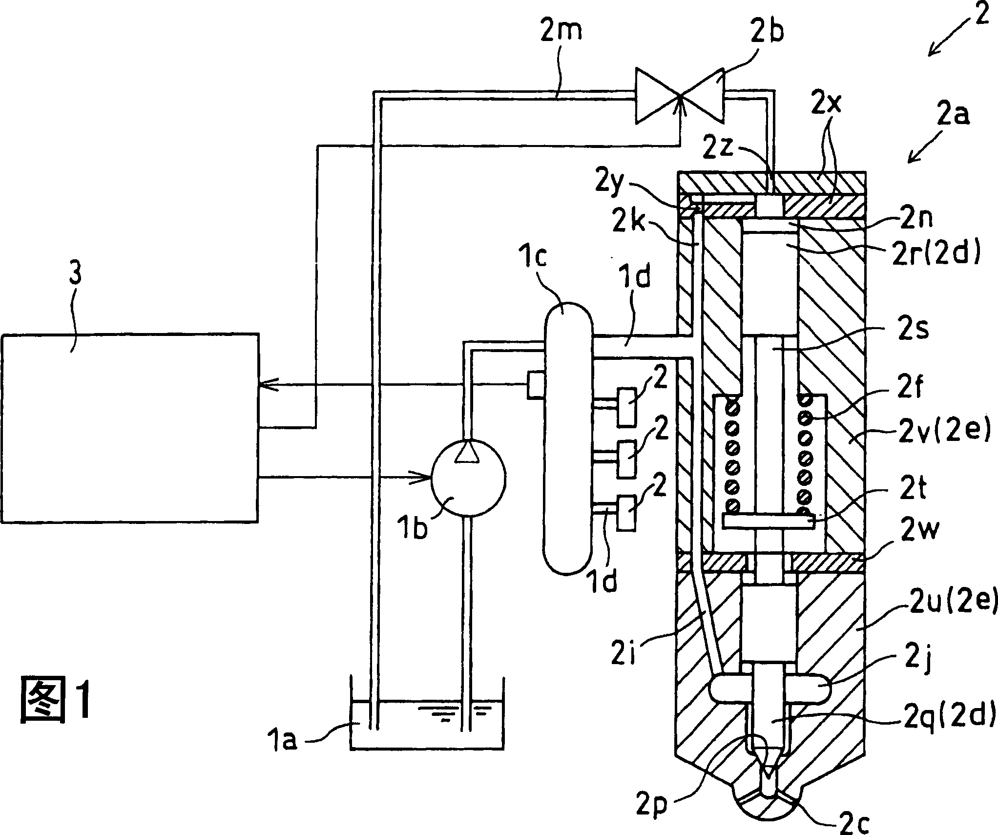
[0040] A fuel injection device of a first embodiment is explained with reference to FIGS. 1 and 2 . The fuel injection device 1 is a device that supplies and injects fuel into each cylinder of a (4-cylinder) diesel engine (hereinafter also referred to as an engine). As shown in FIG. 1, the engine includes: a fuel supply pump 1b, which sucks fuel from a fuel tank 1a and discharges high-pressure fuel; a common rail device 1c, which stores high-pressure fuel and controls fuel pressure with common rail pressure, wherein the fuel is The common rail pressure is used for injection; a plurality of injectors 2, which are installed on each engine cylinder and inject high-pressure fuel into the corresponding cylinder; and an electronic control unit 3, which electronically controls the fuel supply pump 1b, injection Device 2 and so on.

[0041] These injectors 2 are provided on the downstream side of the high-pressure fuel lines 1d branched from the common rail device 1c. The injector 2...


PUM


Abstract

Inside a fuel injection system provided with a fuel injector (2a) and an electromagnetic actuator (2b), a needle valve (2q) of the fuel injector (2a) is lifted directly or indirectly by means of the electromagnetic force generated inside the actuator (2b) so as to open a fuel nozzle (2c). A control unit (3) controls the current fed into the solenoid of the electromagnetic actuator (2b) in the mode; therefore, a peak current (Ip) is fed in at first and then a first constant current and a second constant current (I1, I2) are fed into the solenoid. The target value of the current supply of the first constant current (I1) can be changed into a value basically less than that of a battery voltage. Therefore, the battery voltage does not need to be monitored all the time.

Description

technical field [0001] The present invention relates to a fuel injection system for injecting fuel into an internal combustion engine. Background technique [0002] A fuel injection system of an internal combustion engine has a plurality of injectors provided into respective engine cylinders so as to inject fuel into combustion chambers of the respective engine cylinders. The injector includes: a nozzle body, which has a fuel passage and a fuel nozzle; a needle valve, which is movably mounted in the nozzle body to open and close the fuel nozzle; and an electromagnetic actuator, which directly or indirectly raises the needle valve. rise. [0003] When electric current is supplied into the solenoid of the electromagnetic actuator, electromagnetic force is generated, and thus the needle valve is lifted directly or indirectly by the electromagnetic force, thereby starting fuel injection by opening a fuel injection port. When the supply of electric current to the solenoid is st...

Claims


Application Information

Patent Timeline
Patent Type & Authority Applications(China)
IPC IPC(8): F02D41/04F02D41/26
CPCF02M63/0015F02M47/027F02D2200/503F02D2041/2017H01F7/1844F02D2041/2058F02M63/0225F02D41/20F02M2547/006
Inventor 菊谷享史
Owner DENSO CORP
Why Eureka
Try Eureka