Direct-fluid-supply writing implement
A direct liquid type, pen tool technology, applied in writing tools, other ink pens, printing and other directions, can solve the problems of inability to alternate air and ink, cheap supply, large number of parts, etc., and achieve the effect of simplifying the structure and easy to manufacture.
- Summary
- Abstract
- Description
- Claims
- Application Information
AI Technical Summary
Problems solved by technology
Method used
Image
Examples
no. 1 Embodiment
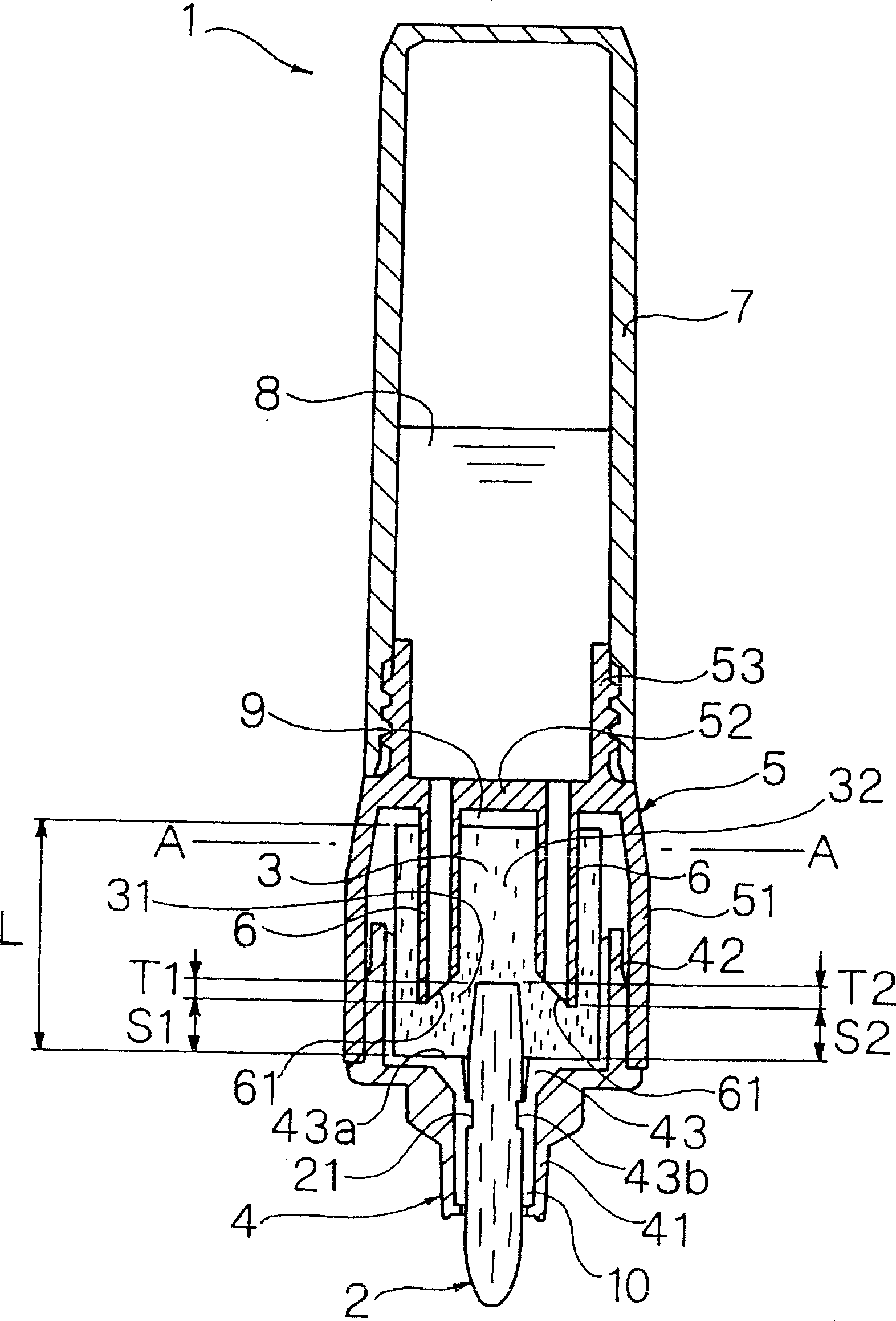
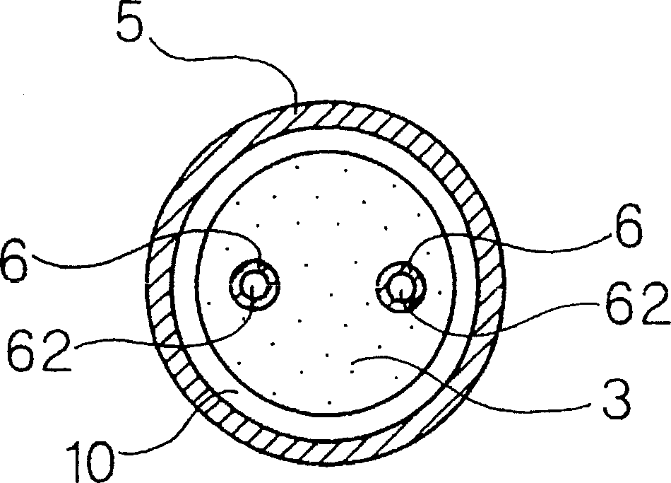
[0217] Figure 1 to Figure 2 A direct fluid writing tool 1 according to a first embodiment of the present invention is shown.
[0218] The direct-liquid pen tool 1 of this embodiment has: a pen tip 2; an ink absorbing body 3 connected to the rear end of the pen tip 2; an absorbing body housing part, which holds the above-mentioned pen tip 2 at the front end and accommodates the above-mentioned ink absorbing body 3 inside; The ink tube 7 is installed at the rear of the above-mentioned absorber housing part, and directly stores the ink 8 inside; the partition 52 divides the above-mentioned absorber housing part and the above-mentioned ink tube 7; and a plurality of (specifically, two) communication tubes 6, It protrudes forward from the front surface of the above-mentioned partition plate 52 , pierces through and is connected to the inside of the ink absorber 3 . The absorber housing portion has a tip member 4 holding the pen tip 2 and an intermediate member 5 connecting the ti...
no. 2 Embodiment
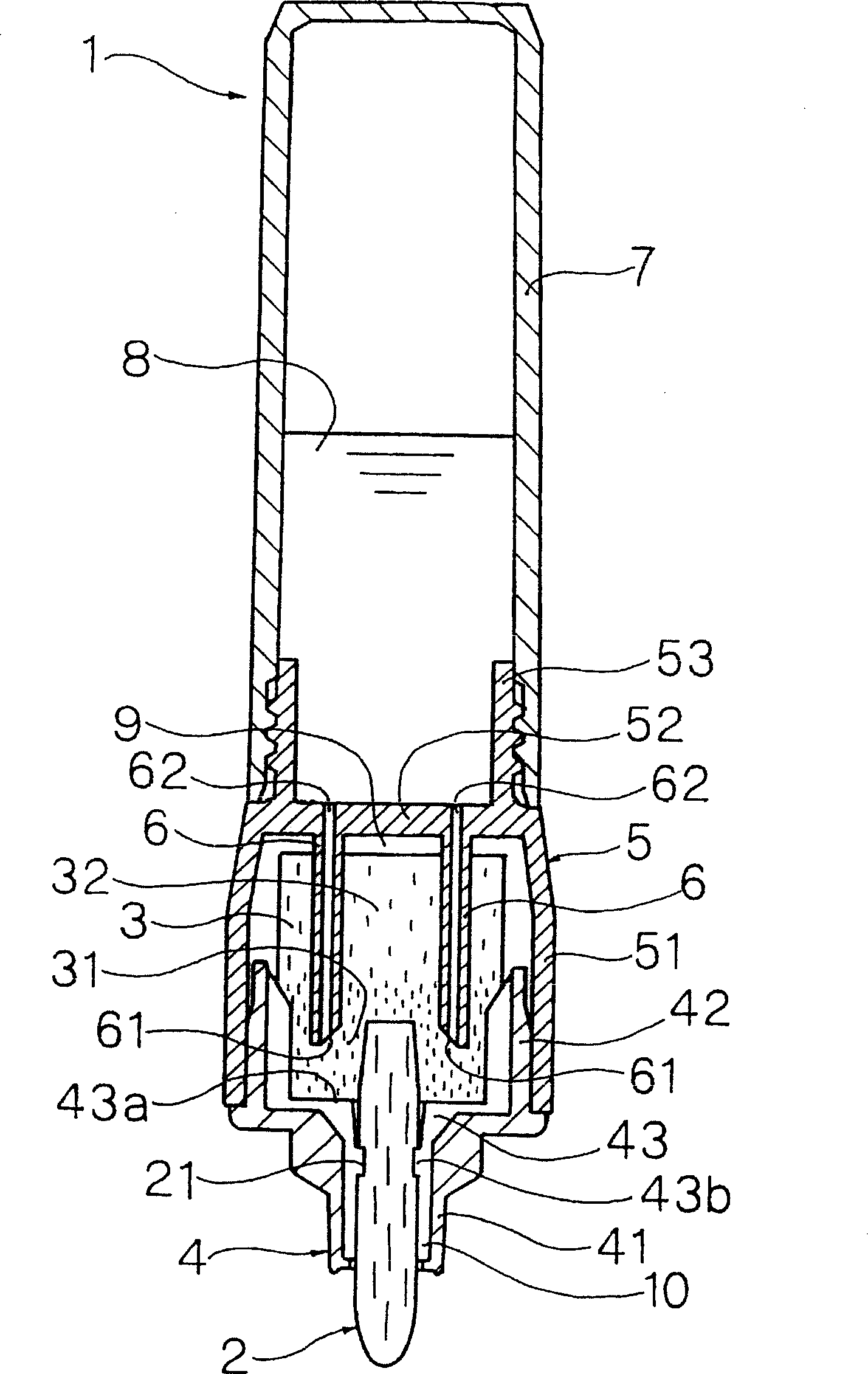
[0241] image 3 Shows the second embodiment of the present invention.
[0242] This embodiment is a modified example of the first embodiment. The difference from the first embodiment is that the high-density portion 31 is formed on the front portion of the ink absorber 3 by pressing and compressing the front outer peripheral surface of the ink absorber 3 inward in the radial direction.
[0243] The diameter of the inscribed circle of the plurality of ribs 43 formed on the inner surface of the large-diameter portion 42 of the front end member 4 is set to be slightly larger than the outer diameter of the front portion of the ink absorber 3 . The above-mentioned ink absorber 3 has a uniform density distribution in the front-rear direction before it is press-fitted into the tip member 4 . In addition, when the front portion of the ink absorber 3 is pressed into the large-diameter portion 42 of the front end member 4, the outer peripheral surface of the front portion of the ink a...
no. 3 Embodiment
[0245] Figure 4 Shows the third embodiment of the present invention.
[0246] This embodiment is a modified example of the first embodiment, and differs from the first embodiment in that a high-density portion 31 is formed at the front of the ink absorber 3 by pressing and compressing the front end of the ink absorber 3 backward.
[0247] On the restricting wall portion 43a of the plurality of ribs 43 formed on the inner surface of the front end member 4, a piercing portion 43c that protrudes large backward is integrally formed. Before the ink absorber 3 is press-fitted into the front end member 4, it has a uniform density distribution in the front-rear direction. And, if the front part of the above-mentioned ink absorbing body 3 is inserted into the large-diameter portion 42 of the above-mentioned front end member 4, the above-mentioned piercing portion 43c is deeply inserted into the front end surface of the above-mentioned ink absorbing body 3, and the front end of the in...
PUM
 Abstract
Description
Claims
Application Information
 - R&D
- Intellectual Property
- Life Sciences
- Materials
- Tech Scout
- Unparalleled Data Quality
- Higher Quality Content
- 60% Fewer Hallucinations
Browse by: Latest US Patents, China's latest patents, Technical Efficacy Thesaurus, Application Domain, Technology Topic, Popular Technical Reports.
© 2025 PatSnap. All rights reserved.Legal|Privacy policy|Modern Slavery Act Transparency Statement|Sitemap|About US| Contact US: help@patsnap.com


