Ball pen tip and aqueous ball point pen using the same

A ballpoint pen tip, water-based technology, applied in the direction of ballpoint pen, pen tip, lighting device, etc., can solve problems such as inability to obtain, offset of handwriting, and penetration of handwriting

Active Publication Date: 2008-08-13
THE PILOT INK CO LTD
View PDF1 Cites 5 Cited by
  • Summary
  • Abstract
  • Description
  • Claims
  • Application Information

AI Technical Summary

Problems solved by technology

However, due to the slightly different (discrete) flow characteristics of the aforementioned water-based ballpoint pen tip with extremely small beads, handwriting bleeding may occur, or handwriting deviation may occur, and it may not be possible to obtain suitable thinner line width handwriting.

Method used


Image

  • Ball pen tip and aqueous ball point pen using the same
  • Ball pen tip and aqueous ball point pen using the same
  • Ball pen tip and aqueous ball point pen using the same

Examples


no. 1 Embodiment

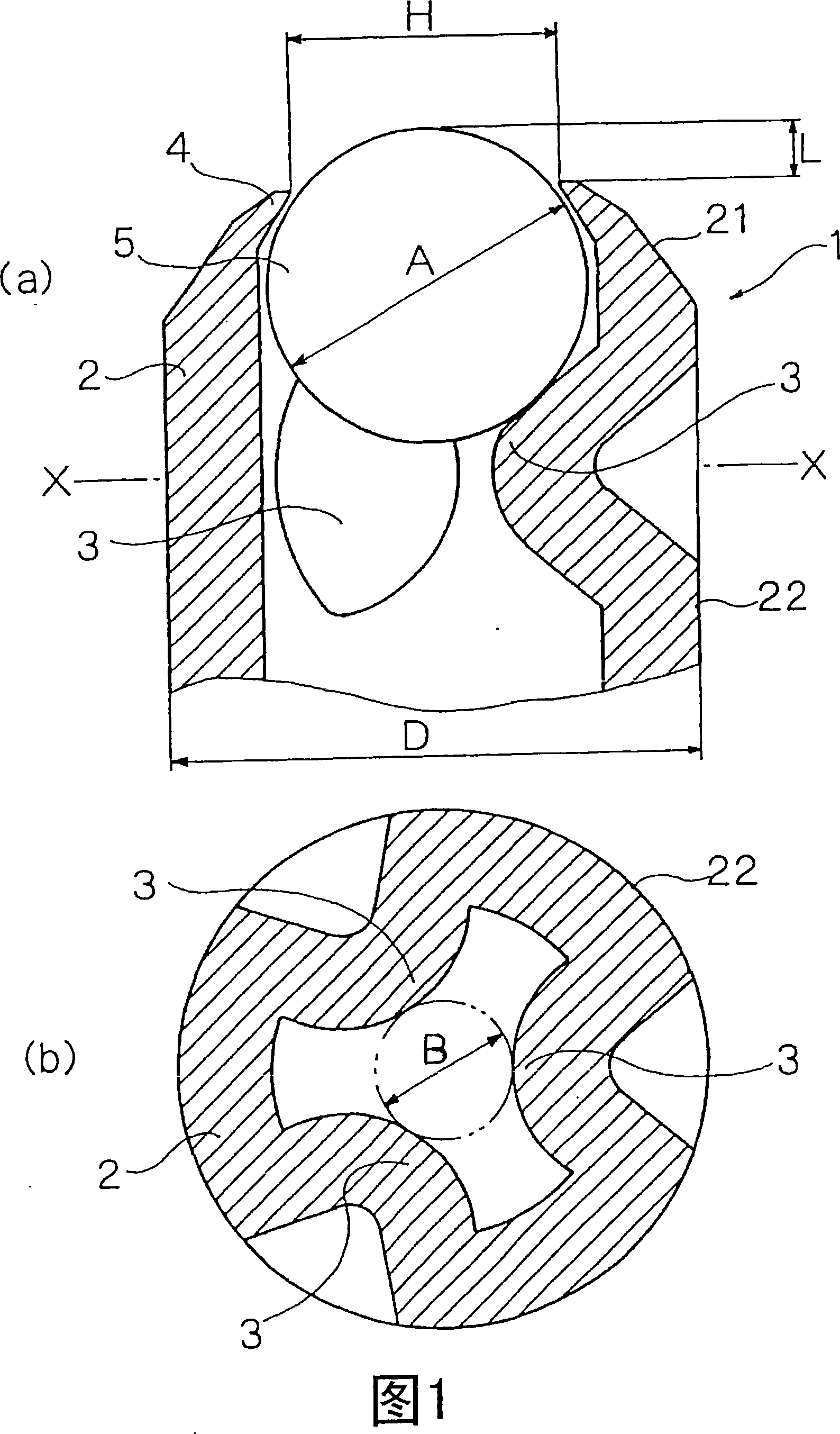
[0144] FIG. 1 shows a first embodiment of a ballpoint pen tip 1 of the present invention. The ballpoint pen tip 1 of this embodiment includes: a straight cylindrical metal body 2 made of SUS321; A (here, 3) internally protruding bead support seat 3; a riveting portion 4 formed by deforming the inside of the front end of the pointed front end portion 21 of the aforementioned metal body 2 into a circumferential shape; rotatably held Hold the bead body 5 between the aforementioned bead body support seat 3 and the aforementioned riveting portion 4 .

[0145] Two types of outer diameters A of 0.25 mm and 0.28 mm were used for the beads 5 . The metal body 2 forms a straight cylindrical portion 22 with a substantially constant outer diameter from the rear end of the pointed front end portion 21 located in front of the bead holder 3 to the rear end of the metal body 2, and becomes needle-shaped. When the outer diameter A of the aforementioned beads 5 is 0.25 mm, the outer diameter D...

no. 2 Embodiment

[0188] FIG. 6 shows a second embodiment of the ballpoint pen 1 of the present invention. The ballpoint pen tip 1 of this embodiment includes: a cylindrical SUS304 metal main body 2 having a pointed front end portion 21, a bead support seat 3 formed on the inner surface near the front end of the metal main body 2 by cutting, The caulking portion 4 formed by deforming the inside of the tip end portion 21 of the metal body 2 into a circumferential shape, and the bead held between the bead support seat 3 and the caulking portion 4 in a rotatable manner. Body 5.

[0189] The pointed tip portion 21 is formed on the outer surface of the tip portion of the metal main body 2 to extend rearward from the caulking portion 4 over the bead holder 3 . A center hole 31 and a plurality (here, three) of ink induction grooves 32 radially communicating with the center hole 31 are provided through the bead holder 3 in the axial direction. Two types of outer diameters A of 0.25 mm and 0.28 mm wer...

no. 3 Embodiment

[0227] 10 to 12 show a third embodiment of the ballpoint pen tip 1 of the present invention.

[0228] (ballpoint pen tip)

[0229] The ballpoint pen tip 1 of this embodiment includes: a straight cylindrical metal main body 2 made of stainless steel (for example, austenitic stainless steel such as SUS321), and includes a A plurality of (here, three) internally protruding bead support seats 3 formed by pressing deformation (press processing) are formed by internally deforming (riveting deformation) the front end of the pointed front end portion 21 of the aforementioned metal body 2. The riveting portion 4 formed in a circumferential shape, the bead holding hole 23 formed between the bead holder 3 and the riveting portion 4, the bead held in the bead holding hole 23 rotatably Body 5.

[0230] The aforementioned bead body 5 adopts a bead body whose outer diameter A is 0.25 mm. The metal main body 2 is formed with a straight cylindrical portion 22 from the rear end of the pointe...


PUM


Abstract

To obtain a ball-point pen tip capable of preventing a ball from falling down for a long period of time even though an extremely small ball is equipped, and having a sufficient writing performance without interruption of handwriting. A ball seat 3 is formed in the inner face near the tip of a metal cylinder 2. A ball 5 with an outer diameter of less than 0.3 mm is stored at the front side of the ball seat 3. A caulking part 4 is formed by deforming the tapered tip part 21 of the metal cylinder 2 inward into a circumferential shape. The ball 5 is rotatably held between the ball seat 3 and the caulking part 4. A part of the ball 5 is projected ahead of the tip of the caulking part 4. When the outer diameter of the ball 5 is A, the inner diameter of the caulking part 4 is H, and the projected dimension of the ball 5 from the tip of the caulking part 4 is L, relations of 0.010 mm B43K 1 / 08 B43K 7 / 00 13 36 2 2005 / 2 / 2 101239550 2008 / 8 / 13 000000000 Pilot Ink Co., Ltd. Japan Ido Mikiya Yamauchi Harumi Sekine Nobuo huangjian feng 72002 NTD Patent & Trademark Agency Ltd. Units 1805-6, 18th Floor, Greenfield Tower, Concordia Plaza, No.1 Science Museum Road, Tsimshatsui, east, Kowloon, Hong Kong 100045 Japan 2004 / 2 / 2 025826 / 2004 Japan 2004 / 7 / 27 218020 / 2004 Japan 2004 / 7 / 27 218021 / 2004 Japan 2004 / 8 / 12 235560 / 2004 Japan 2004 / 11 / 30 347253 / 2004 Japan 2004 / 11 / 30 347254 / 2004 Japan 2004 / 11 / 30 347255 / 2004

Description

[0001] The present invention is a divisional application whose application number is 200510006281.2, the filing date is February 2, 2005, and the title of the invention is "ballpoint pen tip and water-based ballpoint pen using the same". technical field [0002] The present invention relates to a ballpoint pen tip (ball pen chip) with an extremely small bead body (ie, a bead body with an outer diameter of less than 0.3 mm). Background technique [0003] Conventionally, for such a ballpoint pen point, a ballpoint pen point is disclosed in Technical Solution 3 of Patent Document 1, which is formed by pressing and deforming a plurality of places equidistant from the one end in the vicinity of one end of the metal capillary tube. The seat of the inner protrusion, and a bead with a diameter of less than 0.3mm inserted between the inner protrusion and the aforementioned one end, and the edge of the aforementioned one end forms a riveted part by riveting inside, is characterized in ...

Claims


Application Information

Patent Timeline
Patent Type & Authority Applications(China)
IPC IPC(8): B43K1/08B43K7/00
CPCF21V37/0004F21V37/002
Inventor 井户干也山内治巳关根伸雄
Owner THE PILOT INK CO LTD
Why Eureka
Try Eureka