
Method and device for controlling state of brushless direct current motor and brushless direct current motor

A brushed DC motor, state control technology, applied in the direction of motor generator control, control of electromechanical transmission, electronic commutation motor control, etc., can solve problems such as poor system stability, improve reliability and accuracy, improve Effects of robustness, enhanced stationarity, and success rate

Inactive Publication Date: 2017-08-01
GUANGDONG INSPUR BIG DATA RES CO LTD
View PDF8 Cites 0 Cited by
  • Summary
  • Abstract
  • Description
  • Claims
  • Application Information

AI Technical Summary

Problems solved by technology

Generally, an external detection sensor is used to detect the position of the rotor of the brushless DC motor, but because there are more devices in the entire system, the stability of the entire system is not good.

Method used


Image

  • Method and device for controlling state of brushless direct current motor and brushless direct current motor
  • Method and device for controlling state of brushless direct current motor and brushless direct current motor
  • Method and device for controlling state of brushless direct current motor and brushless direct current motor

Examples


Embodiment approach

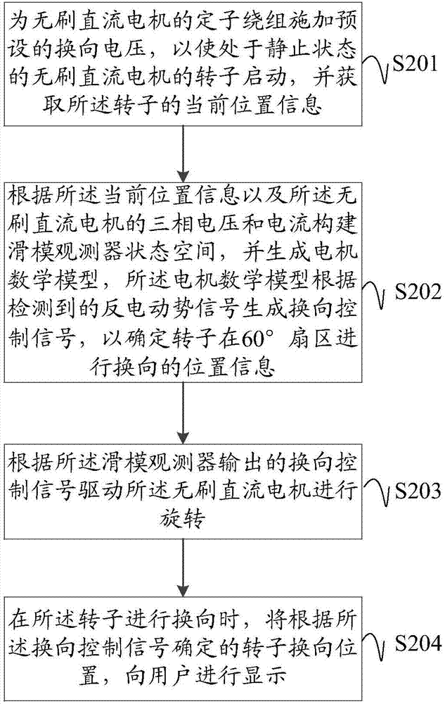
[0055] In a specific embodiment, the state control method of the brushless DC motor may further include:

[0056] S204: When the rotor is commutation, the rotor commutation position determined according to the commutation control signal is displayed to the user.

[0057] The sliding mode observer estimates the back EMF signal at the next position of the rotor based on the current back EMF signal, and can convert the calculated back EMF signal into the position information of the rotor that can be identified by the technicians for display.

[0058] It can be displayed by setting the LCD screen, and of course, it can also be sounded, which does not affect the realization of this application.

[0059] By displaying the position information about to be reversed, it is more convenient for users to check whether the current motor is running normally. When it is found to be running abnormally, the root cause of the problem can be quickly judged, and repairs can be performed as soon as possibl...


PUM


Abstract

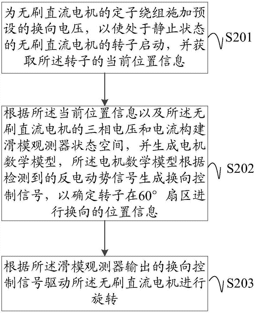
The embodiment of the invention discloses a method for controlling the state of a brushless direct current motor. Commutating voltage is applied to a stator winding of the brushless direct current motor in advance, so that a rotor of the brushless direct current motor in a static state is started, and the current location information of the rotor is acquired; then constructing the state space of a sliding-mode observer according to the current location information of the rotor and three-phase voltage and current, detecting a counter electromotive force signal generated when the current rotor rotates by the sliding-mode observer, using a motor mathematical model to generate a commutation control signal so as to determine the position of the rotor for carrying out commutation in a 60-degree sector, and thus driving the brushless direct current motor to rotate. The smoothness and success rate for motor starting are strengthened, the robustness of the brushless direct current motor is improved, and the reliability and accuracy of motor operation are improved. Moreover, according to a corresponding implementation device and the brushless direct current motor provided by the embodiment of the invention, the method is further of practicability, and the device and the brushless direct current motor have corresponding advantages.

Description

Technical field [0001] The embodiment of the present invention relates to the field of motor technology, and in particular to a state control method and device of a brushless DC motor and a brushless DC motor. Background technique [0002] Brushless DC Motor (BLDCM) combines the advantages of simple DC motor control method, good torque characteristics, good speed regulation performance, simple manufacture of AC motors, no excitation loss, and high power density. It has become a leader in the motor field. Leader. [0003] However, the operation of a brushless DC motor needs to determine the position information of the rotor. The traditional method is to use a position sensor to detect the position of the rotor in real time. However, the volume of the position sensor accounts for an increasing percentage of the volume of the entire motor system, which makes the entire system It is difficult to achieve miniaturization, thus limiting its application in precise and small occasions, and...

Claims


Application Information

Patent Timeline
Patent Type & Authority Applications(China)
IPC IPC(8): H02P21/13H02P21/18H02P6/182
CPCH02P21/13H02P6/182
Inventor 李磊
Owner GUANGDONG INSPUR BIG DATA RES CO LTD
Learn More