Outdoor unit for air conditioner

A technology of air conditioner outdoor unit and outdoor fan, which is applied in air conditioning system, space heating and ventilation, household heating, etc., can solve problems such as difficulty in use, and achieve the effect of increasing power

Inactive Publication Date: 2006-03-29
LG ELECTRONICS (TIANJIN) APPLIANCES CO LTD
View PDF0 Cites 0 Cited by
  • Summary
  • Abstract
  • Description
  • Claims
  • Application Information

AI Technical Summary

Problems solved by technology

[0011] However, the air inlet 13 of the casing 12 of the air conditioner outdoor unit 10 of the conventional technology is formed on the back or side of the casing 12, and the air outlet 14 is formed on the front of the casing 12. or private rooms, etc. are very difficult to use

Method used


Image

  • Outdoor unit for air conditioner
  • Outdoor unit for air conditioner
  • Outdoor unit for air conditioner

Examples


Embodiment Construction

[0042] Embodiments of the present invention will be further described below in conjunction with the accompanying drawings.

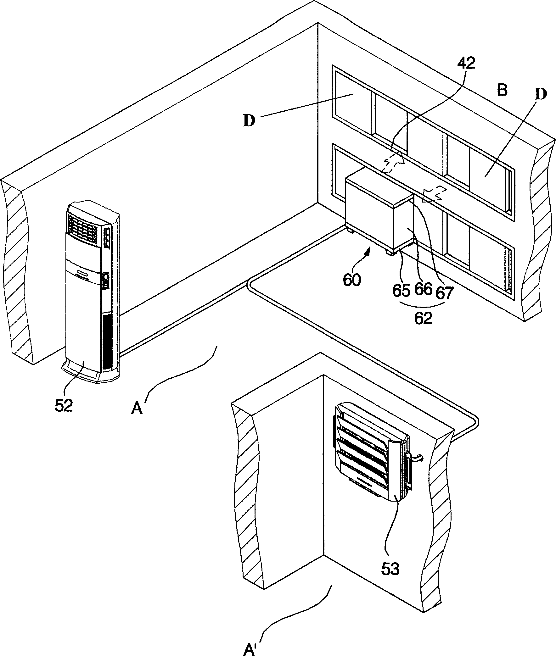
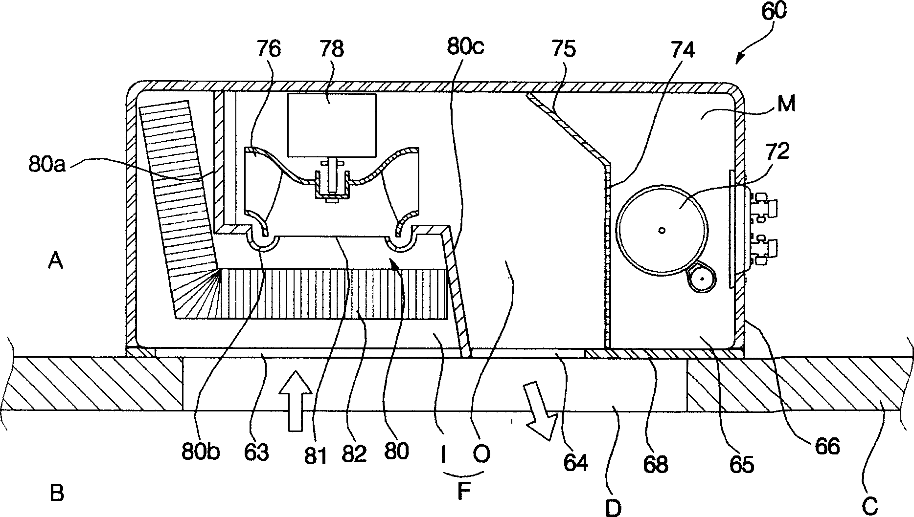
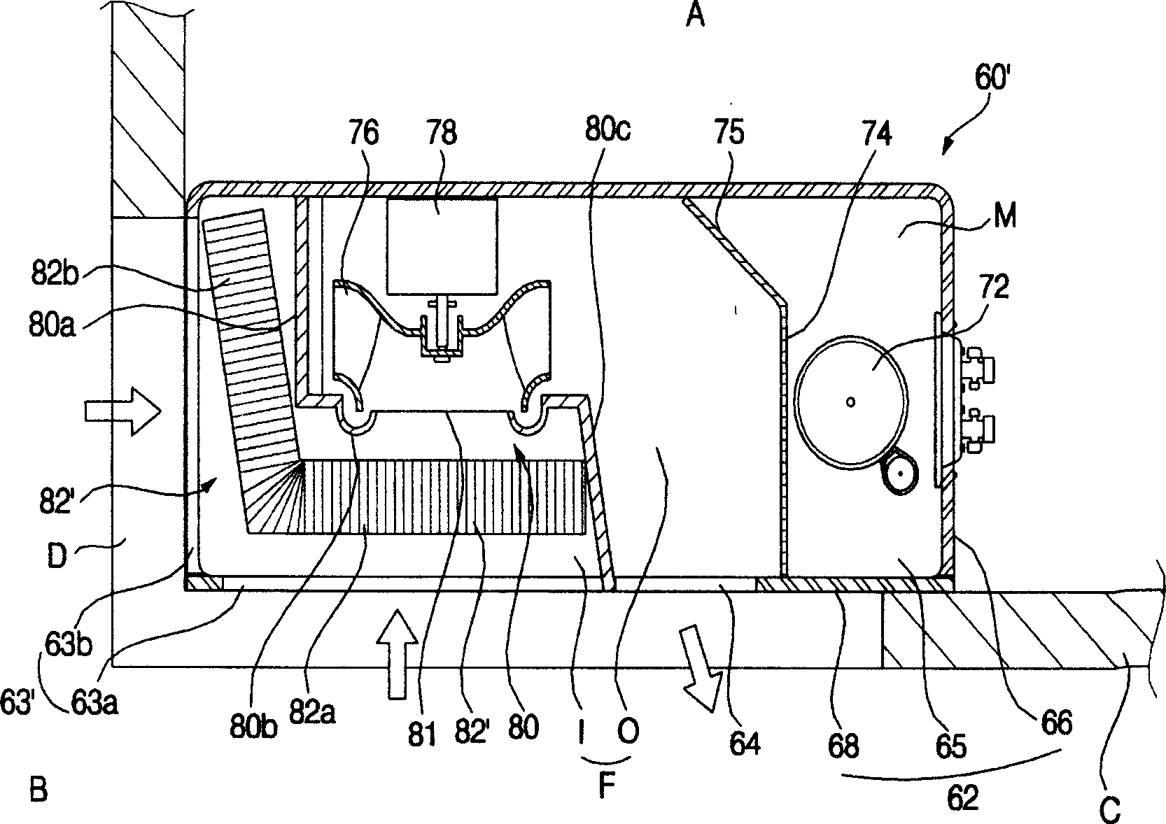
[0043] figure 1 It is a schematic diagram of the installation of the outdoor unit of the air conditioner in the first embodiment of the present invention; figure 2 It is a sectional view of the outdoor unit of the air conditioner according to the first embodiment of the present invention.

[0044] Such as figure 1 As shown, the air-conditioning indoor unit of the present invention is arranged on the ground, or on the wall, or on the ceiling of the indoor A, A' that needs cooling / heating. The indoor unit takes in indoor air, cools / heats the air, and then discharges it indoors.

[0045] Among the above-mentioned indoor units 52 and 53 , one indoor unit 52 may be connected to one outdoor unit 60 , or two or more indoor units 52 and 53 may be connected to one outdoor unit 60 . Hereinafter, the connection between two indoor units 52 and 53 and one outd...


PUM


Abstract

The present invention discloses an outdoor machine of air conditioner, including air suction inlet for sucking air and air discharge outlet for discharging air, the described air suction inlet and air discharge outlet are formed on one side of its external shell.

Description

technical field [0001] The present invention relates to an air conditioner, in particular to an outdoor unit of an air conditioner. Background technique [0002] Generally, an air conditioner is a device that uses a compressor, a condenser, an expansion valve, and an evaporator to circulate a refrigerant, cool or heat the room, and create a comfortable indoor environment. It can be divided into dual-purpose air conditioners with cooling and heating functions and refrigeration air conditioners with only cooling functions. [0003] Cooling and heating dual-purpose air conditioners include the following two types: one is an air conditioner that uses a refrigeration cycle for cooling and uses a separate heater or heating pipe for heating; the other is for switching the direction of refrigerant circulation in the refrigeration cycle , an air conditioner that selectively performs cooling or heating (hereinafter referred to as a heat pump). [0004] In addition, according to whet...

Claims


Application Information

Patent Timeline
Patent Type & Authority Applications(China)
IPC IPC(8): F24F3/00
Inventor 李乃荣
Owner LG ELECTRONICS (TIANJIN) APPLIANCES CO LTD
Why Eureka
Try Eureka