Air supply control method, device and air conditioning unit for realizing circulating air supply

A control method and technology of a control device, applied in mechanical equipment and other directions, can solve problems such as poor results, and achieve better and uniform temperature distribution, reduced air supply wind resistance, and uniform air supply.

Active Publication Date: 2021-07-09
GREE ELECTRIC APPLIANCES INC
View PDF7 Cites 0 Cited by
  • Summary
  • Abstract
  • Description
  • Claims
  • Application Information

AI Technical Summary

Problems solved by technology

[0005] The invention provides an air supply control method, device and air conditioning unit for realizing circulating air supply, so as to at least solve the problem in the prior art that circulating air supply needs to rely on the wall and the effect is not good

Method used


Image

  • Air supply control method, device and air conditioning unit for realizing circulating air supply
  • Air supply control method, device and air conditioning unit for realizing circulating air supply
  • Air supply control method, device and air conditioning unit for realizing circulating air supply

Examples


Embodiment 1

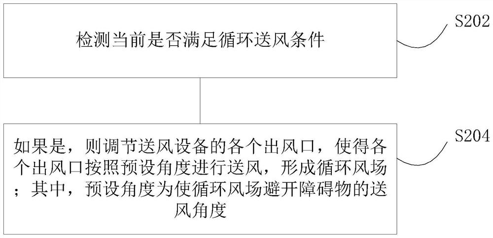
[0025] In the preferred embodiment 1 of the present invention, an air supply control method is provided, which can be directly applied to various air supply equipment, such as fans, air conditioners, fresh air systems, etc. Wind equipment can be realized by installing software, APP, or writing corresponding programs to the controller. Specifically, figure 2 An alternative flowchart showing the method, such as figure 2 As shown, the method includes the following steps S202-S204:

[0026] S202: Detect whether the current circulation air supply condition is satisfied;

[0027] S204: If so, adjust each air outlet of the air supply device so that each air outlet supplies air according to a preset angle to form a circulating wind field; wherein, the preset angle is an air supply angle for the circulating air field to avoid obstacles .

[0028] In the above embodiment, a rotary air supply scheme is designed. By adjusting the air supply, the air outlet is no longer facing the wa...

Embodiment 2

[0053] Based on the air supply control method of the air supply equipment provided in the above-mentioned embodiment 1, an air supply control device is also provided in the preferred embodiment 2 of the present invention, specifically, Figure 4 shows an optional structural block diagram of the device, such as Figure 4 As shown, the device includes:

[0054] A detection module 402, configured to detect whether the current circulation air supply condition is satisfied;

[0055] The air supply module 404 is connected with the detection module 402, and is used to adjust each air outlet of the air supply device if the current condition of circulating air supply is satisfied, so that each air outlet can supply air according to a preset angle to form a circulating air field; Let the angle be the air supply angle for the circulating wind field to avoid obstacles.

[0056] In the above embodiment, a rotary air supply scheme is designed. By adjusting the air supply, the air outlet i...

Embodiment 3

[0066] Based on the air supply control device provided in the above-mentioned embodiment 2, in preferred embodiment 3 of the present invention, an air conditioning unit is also provided, including the above-mentioned air supply control device.

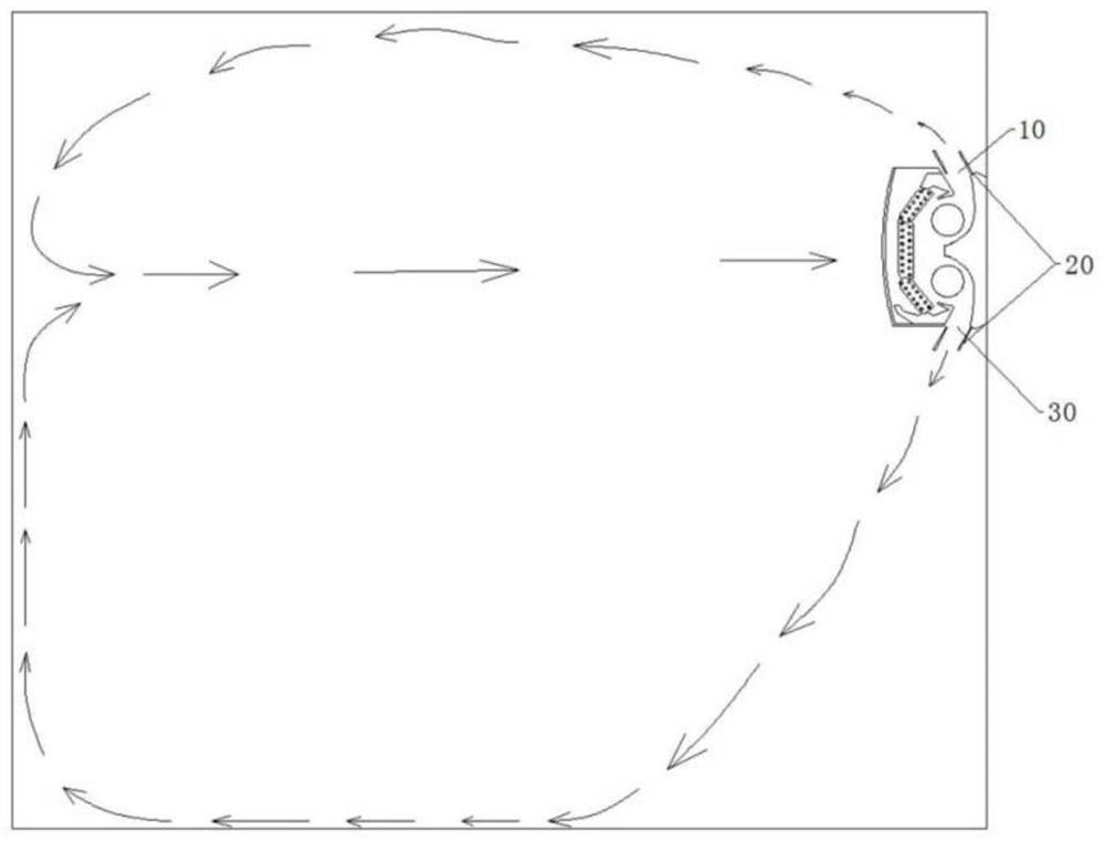
[0067] Preferably, the above-mentioned air-conditioning unit is a patio unit, Figure 5 Show the schematic diagram of the circulating air field formed by the above-mentioned air supply method of the present invention for the patio machine, as Figure 5 As shown, by adjusting the air supply of the patio machine, the air outlet no longer sends air to the wall or the ground, but multiple air outlets, which uniformly supply air in one direction, creating a rotating wind field indoors, driving the whole The air in the room rotates and circulates, and finally forms a rotating airflow like a vortex. The walls or the ground are not on the path of the air supply, so it will not hinder the flow of air, which greatly reduces the resistance of the...


PUM


Abstract

The invention discloses an air supply control method and device for realizing circulating air supply, and an air conditioning unit, wherein the method includes: detecting whether the current condition of circulating air supply is met; if so, adjusting each air outlet of the air supply equipment so that Each air outlet sends air according to a preset angle to form a circulating wind field; wherein, the preset angle is an air supply angle for the circulating wind field to avoid obstacles. The invention solves the problem in the prior art that the circulation air supply needs to rely on the wall and the effect is not good, reduces the wind resistance of the air supply, makes the air supply more uniform, and improves the comfort.

Description

technical field [0001] The invention relates to the technical field of air conditioning, in particular to an air supply control method and device for realizing circulating air supply, and an air conditioner unit. Background technique [0002] At present, the air supply device of the ceiling-mounted air conditioner basically sends air in four fixed directions from the center of the indoor unit. For the same area, the direction and angle of the wind are fixed. However, air conditioners are mostly used in indoor environments, and the air is supplied in a fixed direction. No matter how strong the air supply capacity is, it will eventually be blocked by the indoor walls, thereby increasing the resistance to air circulation. In addition, the ceiling-mounted air conditioner supplies air in four directions, and the four corners where the four air outlet directions meet each other often have no wind at all, or the air volume is low, and it is impossible to achieve a true 360-degree ...

Claims


Application Information

Patent Timeline
Patent Type & Authority Patents(China)
IPC IPC(8): F24F11/89F24F11/79F24F11/64
CPCF24F11/64F24F11/79F24F11/89
Inventor 左攀邹宏亮杨华生吴晋豪解超群
Owner GREE ELECTRIC APPLIANCES INC
Why Eureka
Try Eureka