
Sensing method of coder

An encoder and perceptual encoding technology, which is applied in the direction of encoding, keyboard-like equipment encoding, electrical components, etc., can solve the problems of not being able to perceive the encoder signal, and not being able to perceive the encoder rotation normally.

Inactive Publication Date: 2006-03-29
TAIZHOU LG ELECTRONICS REFRIGERATOR CO LTD
View PDF0 Cites 0 Cited by
  • Summary
  • Abstract
  • Description
  • Claims
  • Application Information

AI Technical Summary

Problems solved by technology

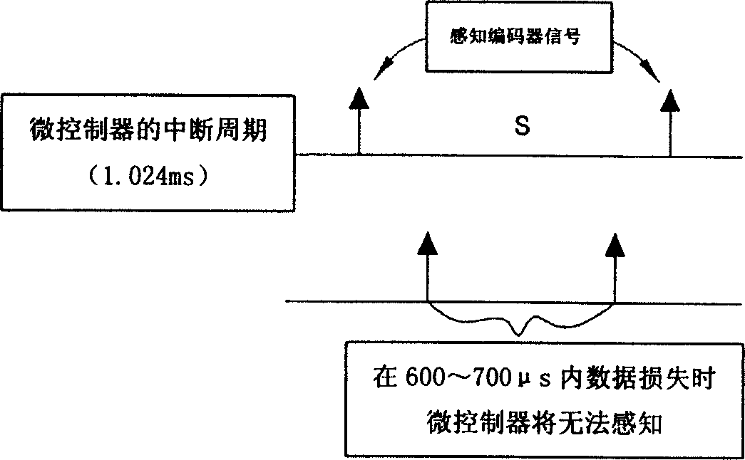
[0007] However, as mentioned above, when the microcontroller senses the rotation of the encoder, as image 3 As shown, the data is read in every 1.024ms, so 2 to 3 out of 10 times cannot perceive the signal of the encoder
[0008] As mentioned above, when sensing the encoder signal in the prior art, the interrupt signal of the microcontroller is relatively longer than the period of the encoder signal. When the data loss of the predetermined period of the encoder signal occurs, the encoder cannot be sensed normally. rotation

Method used


Image

  • Sensing method of coder
  • Sensing method of coder
  • Sensing method of coder

Examples


Embodiment Construction

[0021] like Figure 4 , Figure 5 As shown, referring to the embodiment in which the encoder (20) is installed in the Kimchi refrigerator of the present invention, detailed items (kinds of Kimchi, temperature of Kimchi, etc.) can be selected according to the rotation of the encoder (20). When the encoder (20) is rotated, the signal corresponding to the rotation of the encoder (20) will be transmitted to the microcontroller (10), and the microcontroller (10) senses the rotation of the encoder (20) and selects the required details. item, thereby judging the working condition of the kimchi refrigerator. Meanwhile, the microcontroller (10) controls the operation of the kimchi refrigerator according to the judged conditions (kimchi type and temperature, etc.).

[0022] For this reason, in the present invention, in order to make the micro-controller (10) perceive the encoder signal in every interruption period, the predetermined perception period of the encoder signal is set, wher...


PUM


Abstract

This invention relates to a control method for an encoder including the following steps: designing the output period of the interrupt signal to be shorter than that of the encoder signal, sensing the output period of the encoder signal when the encoder outputs signals and controlling the selection of the related items of the encoder signal sensed in the sensing step in the encoder circuit containing an encoder and a micro-control part outputting the interrupt signals for sensing the encoder signals in a definite period.

Description

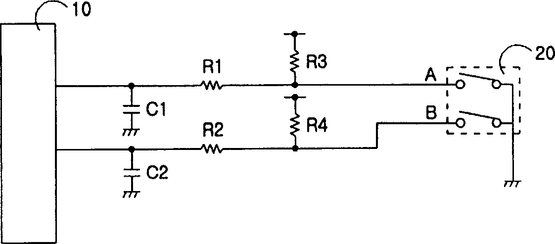
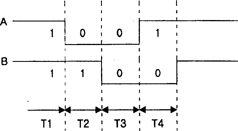
technical field [0001] The invention relates to a perception method of an encoder. Background technique [0002] like figure 1 As shown, first observe the connection relationship of the loop. An encoder (20) with two contacts (A, B) is arranged on the circuit, and each contact A, B of the encoder (20) is connected to the microcontroller (10). In addition, a first resistor (R1) is connected between the contact A of the encoder (20) and the microcontroller (10), and a first resistor (R1) is connected between the contact A of the encoder (20) and the first resistor (R1). 3 resistors (R3), and the other end of the third resistor (R3) is added with an external power supply. A first capacitor (C1) is connected between the first resistor (R1) and the microcontroller (10), and the other end of the first capacitor (C1) is grounded. [0003] At the same time, the second resistor (R2) is connected between the contact B of the above-mentioned encoder (20) and the microcontroller (10...

Claims


Application Information

Patent Timeline
IPC IPC(8): H03M11/00
Inventor 孙才浩
Owner TAIZHOU LG ELECTRONICS REFRIGERATOR CO LTD
Learn More