Ultrasonic diagnostic apparatus and image data generating method

a diagnostic apparatus and ultrasonic technology, applied in diagnostics, medical science, instruments, etc., can solve the problems of difficult to obtain high-resolution image data of deeply existing organs remote from ultrasonic probes, difficult to accurately extract only harmonic components with filtering methods, and poor s/n ratio of image data generated on the basis of harmonic components. , to achieve the effect of improving the sensitivity of receiving thi, satisfying resolution, and reducing the number of artifacts

Active Publication Date: 2017-01-03
TOSHIBA MEDICAL SYST CORP
View PDF9 Cites 0 Cited by
  • Summary
  • Abstract
  • Description
  • Claims
  • Application Information

AI Technical Summary

Benefits of technology

[0016]The present invention has been made in light of the conventional situations, and it is an object of the present invention to provide an ultrasonic diagnostic apparatus and an image data generating method which generate ultrasonic image data with satisfactory resolution and fewer artifacts by improving receiving sensitivity in THI without deviating from the range of exothermic regulation and sound output regulation.
[0019]The present invention as described above makes it possible to generate ultrasonic image data with satisfactory resolution and fewer artifacts since receiving sensitivity in THI is improved without deviating from the range of exothermic regulation and sound output regulation.

Problems solved by technology

However, in the case where the fundamental and harmonic components have broadband spectra, since respective parts of the components overlap with each other, accurately extracting only the harmonic component with the filtering method is difficult.
With such a reason, THI image data generated on the basis of the harmonic component has a poorer S / N ratio than that of an image data generated mainly from the conventional fundamental component (i.e., an image data generated from the fundamental and harmonic components), and in particular, it is difficult to obtain a high-resolution image data of a deeply existing organ remote from the ultrasonic probe.
While two methods for improving the S / N ratio of the receiving harmonic component are provided: one for reducing noises (N) in a receiving circuit and the other for improving the receiving intensity of a signal component (S), since the former one has already reached the limit for the duty, the S / N ratio cannot be improved without the help of the latter one.
While the receiving sensitivity of the harmonic component could be improved by increasing a transmission sound output of the apparatus, when the transmission sound output is increased with a method similar to the conventional one, it is difficult to comply with the heat generation and sound output regulations of the ultrasonic probe set while taking into account the safety of the subject.

Method used


Image

  • Ultrasonic diagnostic apparatus and image data generating method
  • Ultrasonic diagnostic apparatus and image data generating method
  • Ultrasonic diagnostic apparatus and image data generating method

Examples


Embodiment Construction

[0032]The present invention will now be described in further detail below with reference to an embodiment in conjunction with the accompanying drawings.

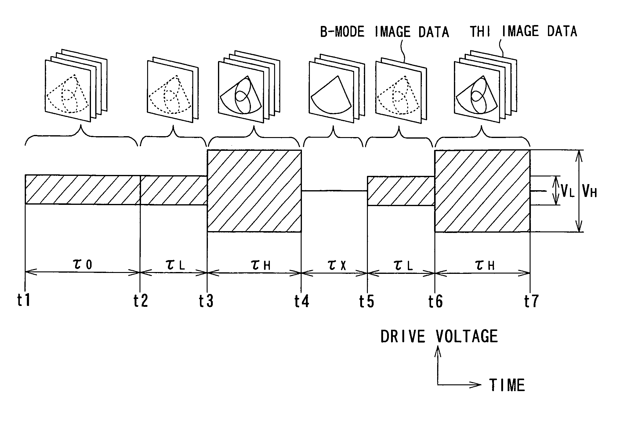
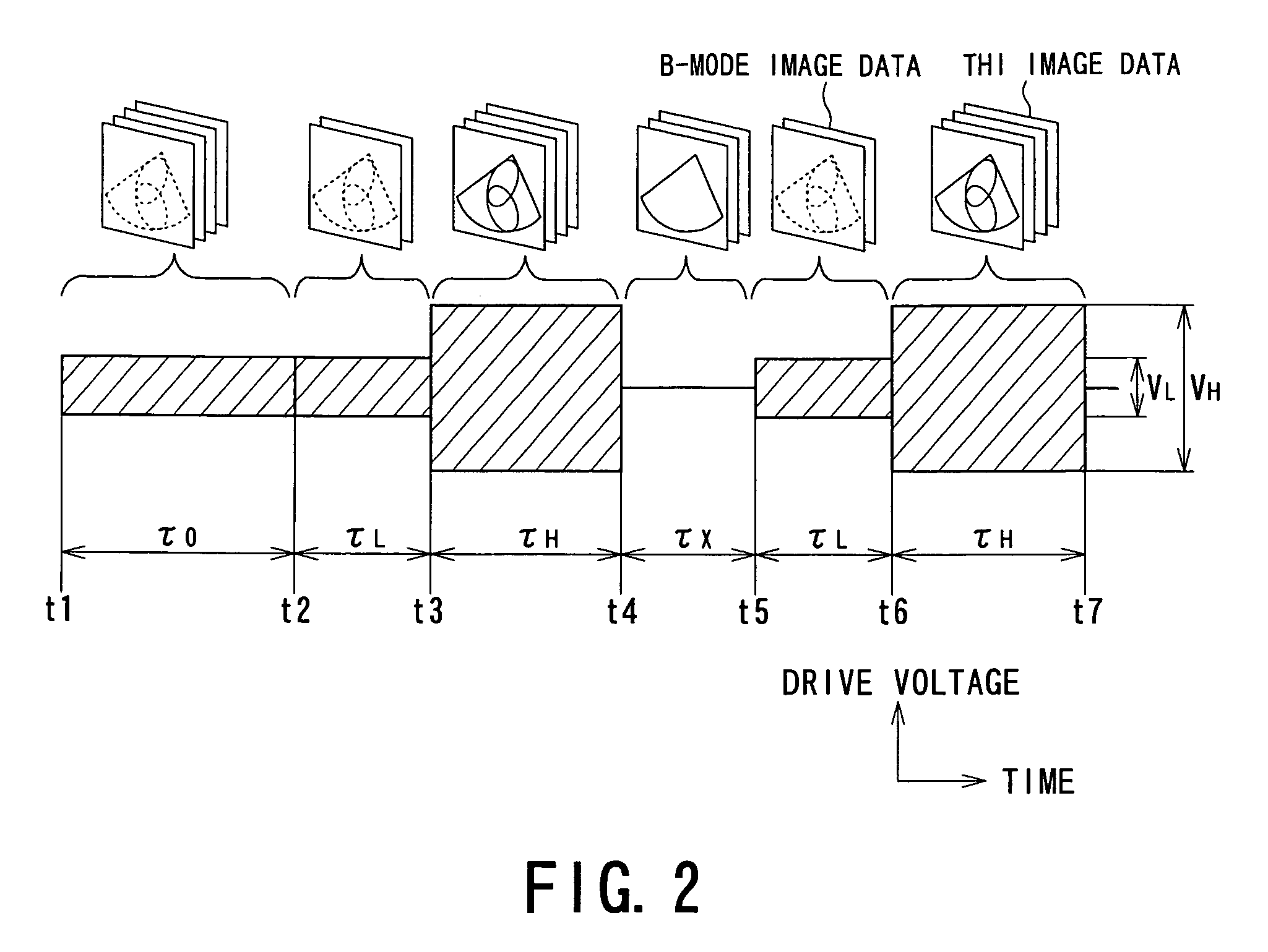
[0033]The embodiment of the present invention has a feature in inhibiting a transmission sound output and heat generation of an ultrasonic probe in a unit time within the respective regulation ranges of the sound output and the heat generation by repeating (a) a transmission of ultrasonic waves for a B-mode image with low sound pressure intended for monitoring, e.g., an operation of an apparatus and an imaging position (an image-data generating position), (b) a transmission of ultrasonic waves for a THI image with high sound pressure intended for generating diagnostic image data, and (c) a transmission with zero sound pressure intended for suspending a transmission of ultrasonic waves, all in respective predetermined periods.

[0034]While THI image data in the present embodiment is generated by applying envelope detection to the harmon...


PUM


Abstract

An ultrasonic diagnostic apparatus comprises a driving unit, a nonlinear component extracting unit, a first image data generating unit, a second image data generating unit and a control unit. The driving unit drives an ultrasonic transducer to transmit an ultrasonic wave to a subject. The nonlinear component extracting unit extracts a nonlinear component corresponding to the ultrasonic wave from a reception signal received by the ultrasonic transducer. The first image data generating unit generates a first image data based on the nonlinear component. The second image data generating unit generates a second image data based on the reception signal. The control unit arbitrarily distributes a sound output for transmission in a definite period of time to a first ultrasonic transmission for generating the first image data and a second ultrasonic transmission for generating the second image data.

Description

BACKGROUND OF THE INVENTION[0001]1. Field of the Invention[0002]The present invention relates to an ultrasonic diagnostic apparatus and an image data generating method, and more particularly, to an ultrasonic diagnostic apparatus and an image data generating method which obtain ultrasonic image data with high resolution by detecting harmonic component of an ultrasonic reflected wave from a subject.[0003]2. Description of the Related Art[0004]An ultrasonic diagnostic apparatus serves so as to emit an ultrasonic wave generated by an ultrasonic transducer built in an ultrasonic probe into a subject, receive a reflective wave generated due to a difference in sound impedances of subject tissues by the ultrasonic transducer and display it on a monitor.[0005]An ultrasonic diagnosis is widely used for a function test of a heart or the like, or a morphological diagnosis of a variety of organs since a two-dimensional image can be easily observed in real time by simply contacting an ultrasonic...

Claims


Application Information

Patent Timeline
Patent Type & Authority Patents(United States)
IPC IPC(8): A61B8/00A61B8/14G01S7/52
CPCA61B8/546A61B8/14G01S7/52023G01S7/52026G01S7/52038G01S7/52063
Inventor TAKIMOTO, MASAO
Owner TOSHIBA MEDICAL SYST CORP
Why Eureka
Try Eureka