Automatic frequency control circuit and automatic frequency control method
A technology of automatic frequency control and circuit, applied in the field of automatic frequency control circuit and automatic frequency control, which can solve the problems of speculative characteristic degradation, difficult frequency deviation correction, frequency deviation, etc.
- Summary
- Abstract
- Description
- Claims
- Application Information
AI Technical Summary
Problems solved by technology
Method used
Image
Examples
Embodiment 1
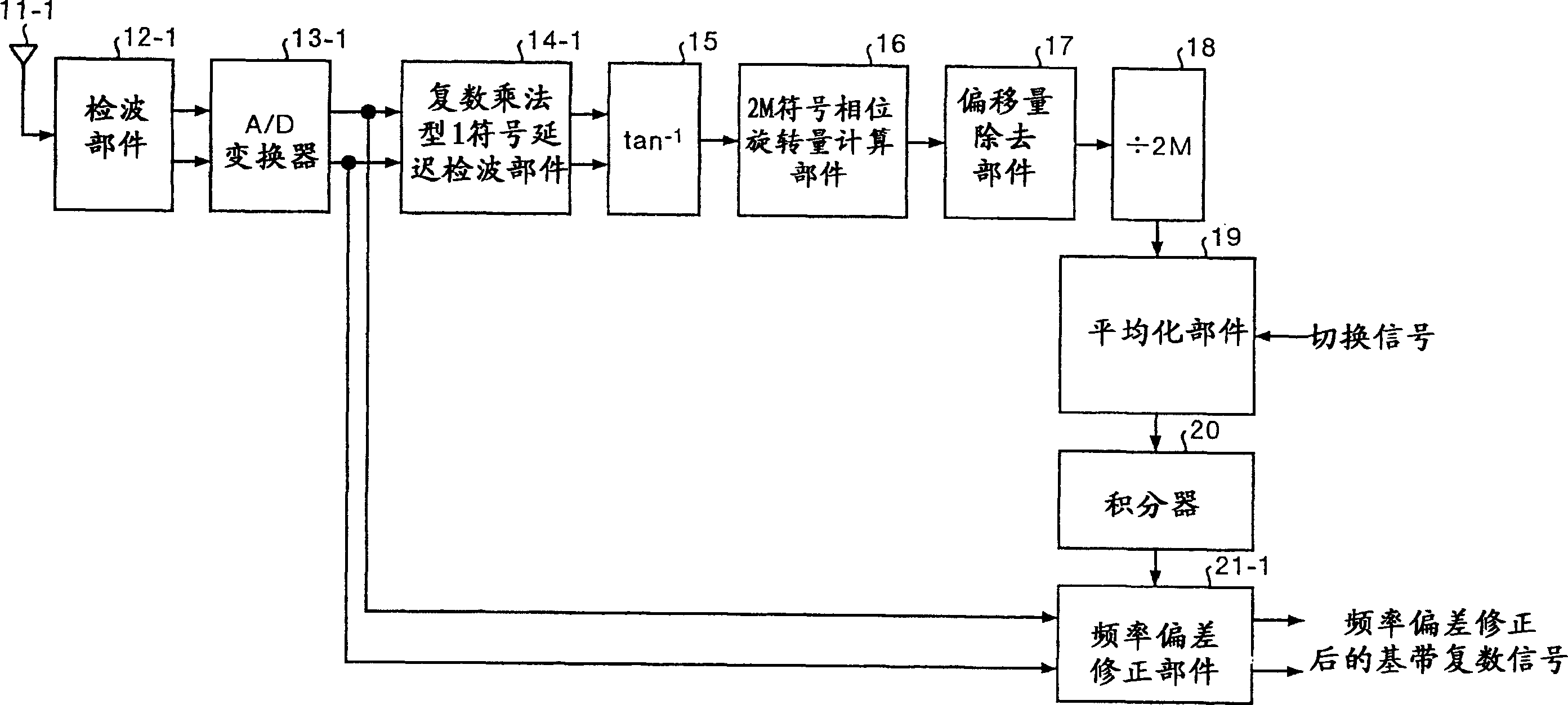
[0039] In Embodiment 1 of the present invention, an automatic frequency control circuit and an automatic frequency control method for correcting a frequency offset by receiving a PSK-modulated signal of data including a header signal of two symbol periods with one receiving antenna will be described.
[0040] figure 2 It is a block diagram showing the configuration of an example of an automatic frequency control circuit according to Embodiment 1 of the present invention. exist figure 2Among them, the automatic frequency control circuit is composed of a pre-processing unit, an offset removal unit 17, and a correction data generation unit. The pre-processing unit is composed of a complex multiplication type 1-symbol differential detection unit 14 - 1 , an inverse inverse unit 15 and a 2M-symbol phase rotation amount calculation unit 16 . The correction data generation unit is composed of a division unit 18, an integrator 20, and a frequency deviation correction unit 20-1.
...
Embodiment 2
[0110] In this second embodiment, an automatic frequency control circuit and an automatic frequency control circuit for correcting frequency deviation by receiving a PSK-modulated signal of data including a preamble signal of two symbol periods with two or more receiving antennas will be described. method.
[0111] Furthermore, in the automatic frequency control circuit of the second embodiment, a circuit for combining signals received by a plurality of antennas is added to the automatic frequency control circuit of the first embodiment described above.
[0112] 8 is a block diagram showing the configuration of an example of an automatic frequency control circuit having N (N is a natural number equal to or greater than 2) receiving antennas. In FIG. 8 , the automatic frequency control circuit includes: a front end composed of N complex multiplication type 1-symbol delay detection units 14-1 to 14-N, an adder 23, an inverse inversion unit 15, and a 2M-symbol phase rotation calc...
Embodiment 3
[0139] In the present embodiment 3, for the PSK-modulated signal having the data format with a preamble signal of 2 symbol periods added at the beginning, it is received with one receiving antenna, and the automatic signal shown in embodiment 1 is used when the preamble signal is received. The frequency control circuit performs high-precision frequency deviation estimation in a short period of time, and switches operation when the received signal transitions from the preamble signal to random data, and performs frequency deviation estimation using the estimated frequency deviation when the preamble signal is received as an initial value. Thus, it is possible to provide an automatic frequency control circuit having high-speed and high-precision frequency deviation estimation and good frequency deviation tracking characteristics.
[0140] Figure 10 It is a block diagram showing the configuration of the automatic frequency control circuit of Embodiment 3 having one receiving ant...
PUM
 Abstract
Description
Claims
Application Information
 - Generate Ideas
- Intellectual Property
- Life Sciences
- Materials
- Tech Scout
- Unparalleled Data Quality
- Higher Quality Content
- 60% Fewer Hallucinations
Browse by: Latest US Patents, China's latest patents, Technical Efficacy Thesaurus, Application Domain, Technology Topic, Popular Technical Reports.
© 2025 PatSnap. All rights reserved.Legal|Privacy policy|Modern Slavery Act Transparency Statement|Sitemap|About US| Contact US: help@patsnap.com


