Path detection device and path detection method

A path detection and path technology is applied in the field of path detection devices that use delay distribution to detect fundamental waves and delayed waves, and can solve the problems of received signal detection, increased computational complexity, and received data errors.

Inactive Publication Date: 2006-04-19
PANASONIC CORP
View PDF1 Cites 0 Cited by
  • Summary
  • Abstract
  • Description
  • Claims
  • Application Information

AI Technical Summary

Problems solved by technology

[0006] However, in the conventional path detection device and path detection method, when the maximum value detection method is used in the path detection method, since the maximum value and the maximum value of the number of high-ranked pointers can be reliably detected, the path detection accuracy is high, but There is a problem that the delay profile must be scanned the same number of times as the number of pointers, resulting in an increase in the amount of computation
[0007] On the other hand, when the maximum value detection method is used in the path detection method, although the amount of calculation is reduced, such as figure 1 As shown in , when there are paths at 1-chip intervals, sample S2 is originally a path that should be selected as a delayed wave, but since sample S2 is not a maximum value, it is not selected as a path, so the received signal cannot be detected sufficiently while receiving an error in the data
Especially when communicating in an environment where multipath is likely to occur due to many obstacles, such as indoors, sometimes a delayed wave that is only slightly slower than the fundamental wave may be measured, and errors may occur in received data in an environment where multipath occurs. more probable problem

Method used


Image

  • Path detection device and path detection method
  • Path detection device and path detection method
  • Path detection device and path detection method

Examples


Embodiment approach 1

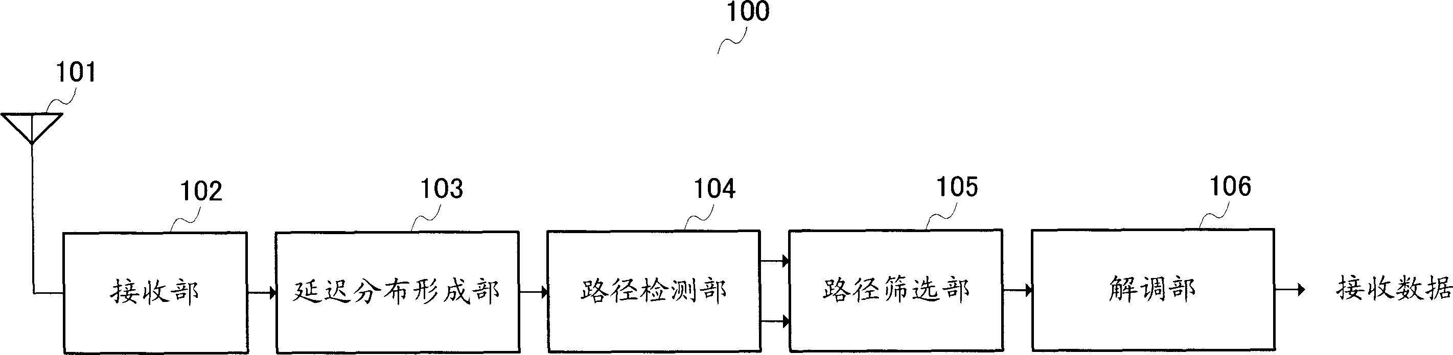
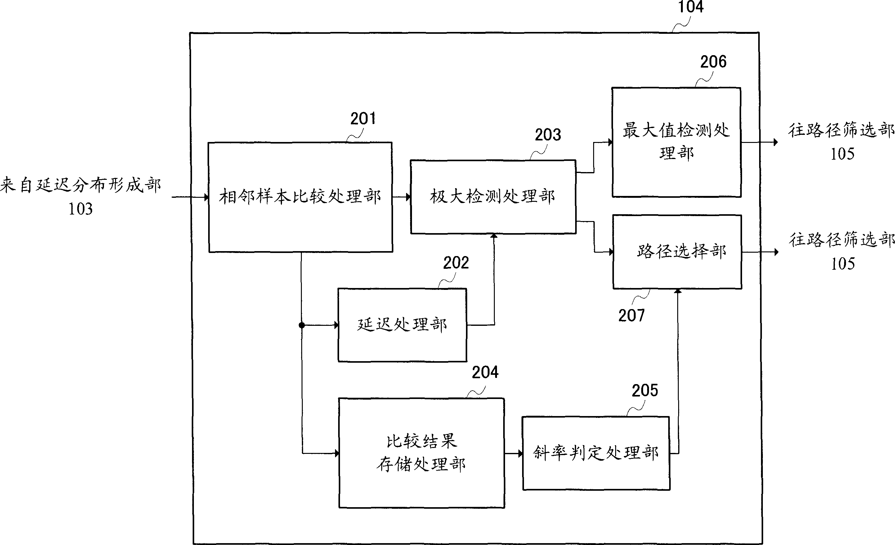
[0025] figure 2 It is a block diagram showing the configuration of the receiving device 100 including the path detection device according to Embodiment 1 of the present invention. exist figure 2 Among them, the path detection device includes a path detection unit 104 and a path screening unit 105 .

[0026] The demodulation device includes: a delay profile formation unit 103 , a path detection unit 104 , a path selection unit 105 , and a demodulation unit 106 .

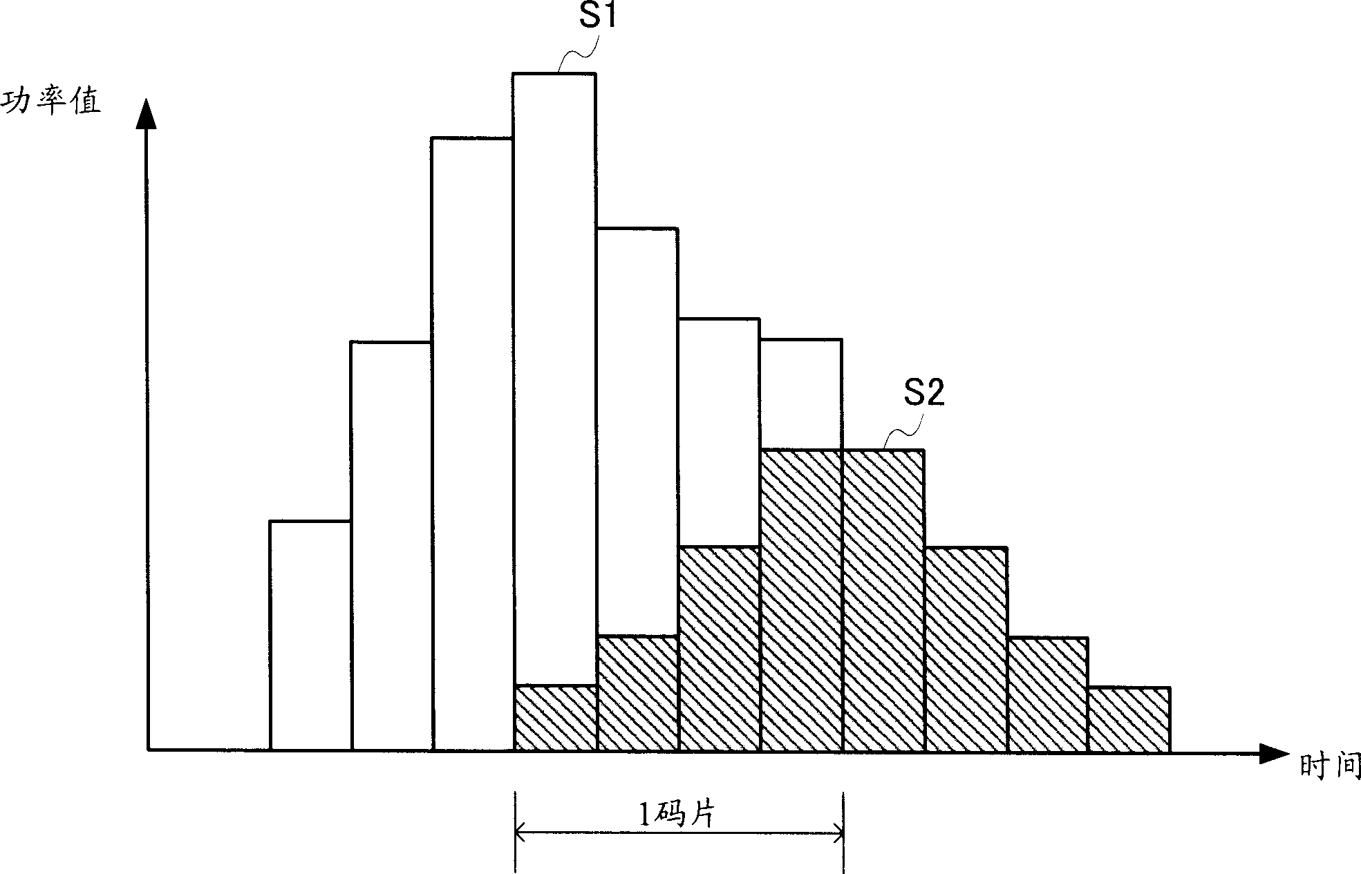
[0027] The reception unit 102 performs processing to down-convert the reception signal received by the antenna 101 from a radio frequency to a baseband frequency or the like. Furthermore, the receiving unit 102 oversamples the received signal by the number of samples of 4 per chip, and outputs the received signal to the delay profile forming unit 103 . However, the oversampling number is generally 2 or 4, but it is not limited to 2 or 4 and can be set to an arbitrary sampling number.

[0028] The delay profile f...

Embodiment approach 2

[0074] Figure 9 It is a diagram showing the configuration of the route detection unit 801 according to Embodiment 2 of the present invention. In this Embodiment 2 Figure 9 in, right with image 3 Parts with the same configuration are given the same reference numerals and their descriptions are omitted. In addition, in the second embodiment, due to the structure of the receiving device and figure 2 Since they have the same structure, description thereof will be omitted.

[0075] The maximum detection processing unit 203 compares the size comparison result information of the previous sample each time the size comparison result information is input from the adjacent sample comparison processing unit 201 . That is to say, when the size comparison result information of the previous sample is information indicating "true" and the size comparison result information of the current sample is information indicating "false", the previous sample is determined to be a maximum value,...

Embodiment approach 3

[0091] Figure 12 It is a diagram showing the configuration of the receiving device 1100 according to Embodiment 3. The receiving device 1100 has a path detection unit 1101 instead of figure 2 The path detection unit 104 of the receiving device 100 according to the first embodiment is shown. In addition, in Figure 12 in, for and figure 2 Parts with the same configuration are given the same reference numerals and their descriptions are omitted.

[0092] The route detection device includes a route detection unit 1101 and a route screening unit 105 . Furthermore, the demodulation device includes a delay profile formation unit 103 , a path detection unit 1101 , a path selection unit 105 , and a demodulation unit 106 .

[0093] The path detection unit 1101 detects the maximum value of the delay profile using the delay profile sequentially input for each sample from the delay profile formation unit 103 , and selects the detected maximum value as a path. Furthermore, when th...


PUM


Abstract

An adjacent sample comparison processor (201) compares power values of adjacent samples of a delay profile created according to a reception signal over-sampled and detects whether the power value is increasing or decreasing. If the comparison result is identical to the increase / decrease information on the power values between adjacent samples at the previous time, a comparison result storage processor (204) adds 1. If the comparison result is different, the comparison result storage processor (204) performs a reset and newly sets 1. When the count of the comparison result storage processor (204) has become identical to the over-sampling number, a slope judgment processor (205) controls a path selection section (207) so as to select a corresponding sample as a path. The path selection section (207) selects a relative maximum sample as a path candidate and also selects the sample instructed by the slope judgment processor (205) as a path. Thus, it is possible to reduce the calculation amount when selecting a path, assure a path selection, and reduce the reception data error ratio.

Description

technical field [0001] The present invention relates to a path detection device and a path detection method, in particular to a path detection device and a path detection method which use delay distribution to detect a fundamental wave and a delayed wave. Background technique [0002] Conventionally, path detection methods using delay profiles include a maximum value detection method and a maximum value detection method. [0003] The maximum value detection method is a method of selecting, as a path, a sample whose power value is the largest in each element (sample) of the delay profile. That is to say, use the maximum value detection of the delay distribution, extract the detected samples and process them, so that the 1 chip interval before and after the detection sample is included (when K samples are oversampled, K-1 before and after the detection sample The power of the interval) is 0, and the detection of the candidate path is performed by repeating the detection of th...

Claims


Application Information

Patent Timeline
Patent Type & Authority Applications(China)
IPC IPC(8): H04B1/707H04J13/00H04B1/7117
CPCH04B1/7113
Inventor 佐佐木大三中胜义反保英明
Owner PANASONIC CORP
Why Eureka
Try Eureka