
Projection image display apparatus and projection optical unit to be used therein

An image display device and image display technology, which are applied to optical elements, optics, projection devices, etc., can solve the problems of small depth of image display devices, large lens diameters, and difficulties in manufacturing optical units, so as to reduce trapezoidal distortion and The effect of small optical depth

Active Publication Date: 2006-05-10
MAXELL HLDG LTD
View PDF3 Cites 5 Cited by
  • Summary
  • Abstract
  • Description
  • Claims
  • Application Information

AI Technical Summary

Problems solved by technology

Thus, it becomes further difficult to manufacture an optical unit that satisfies this requirement
In addition, related to this, it is necessary to increase the required lens diameter
That is, in the optical system of the prior art described above, it is difficult to make the depth of the projection optical unit, and thus the image display device, smaller.

Method used


Image

  • Projection image display apparatus and projection optical unit to be used therein
  • Projection image display apparatus and projection optical unit to be used therein
  • Projection image display apparatus and projection optical unit to be used therein

Examples


Embodiment 1

[0071] use attached Figure 5 ~ Figure 7 and Figure 12 , and further the numerical values ​​shown in Table 1 below, to describe Example 1 of the present invention. Figure 5 A ray diagram of Example 1 is shown. That is, light emitted from the image display element 31 arranged on the lower side of the figure passes through the first optical system 32 composed of a plurality of refracting lenses. Thereafter, reflection is performed by the first free-form surface mirror 33 and further the second free-form surface mirror 34 constituting the second optical system. And it is reflected by the surface of the back mirror 35 which is a plane mirror, and is incident on the screen 36.

[0072] Here, the above-mentioned first optical system is a coaxial optical system composed entirely of axisymmetric refractive surfaces, and four of these refractive surfaces are composed of axisymmetric aspherical surfaces, and the others are composed of spherical surfaces. In addition, the axisymmet...

Embodiment 2

[0098] Next, use the attached Figure 8-10 and 12, and further Table 4 to Table 6 shown below, the second embodiment of the optical unit is described in detail below.

[0099] first, Figure 8 A ray diagram of Example 2 is shown. That is, light emitted from the image display element 41 arranged on the lower side of the figure passes through the first optical system 42 including a plurality of refractive lenses. After that, it passes through the first free-form mirror 43 of the second optical system, and is further reflected by the second free-form mirror 44 . And, it is reflected by the back mirror 45 which is a plane mirror, and is incident on the screen 46 .

[0100] Here, the above-mentioned first optical system is a coaxial optical system composed entirely of axisymmetric refractive surfaces, and four of these refractive surfaces are composed of axisymmetric aspheric surfaces, and the others are composed of spherical surfaces. In addition, the axisymmetric aspheric sur...


PUM


Abstract

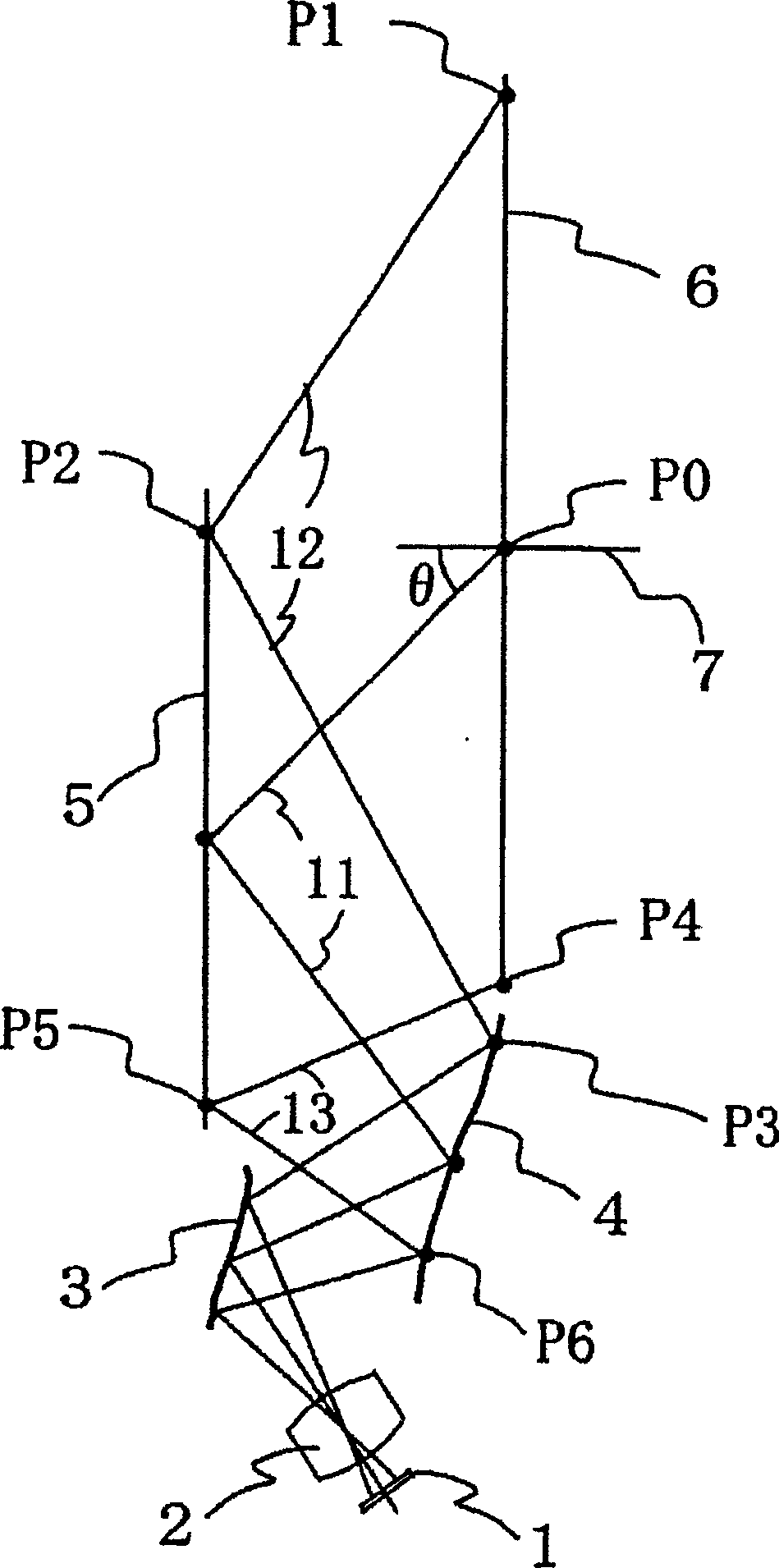
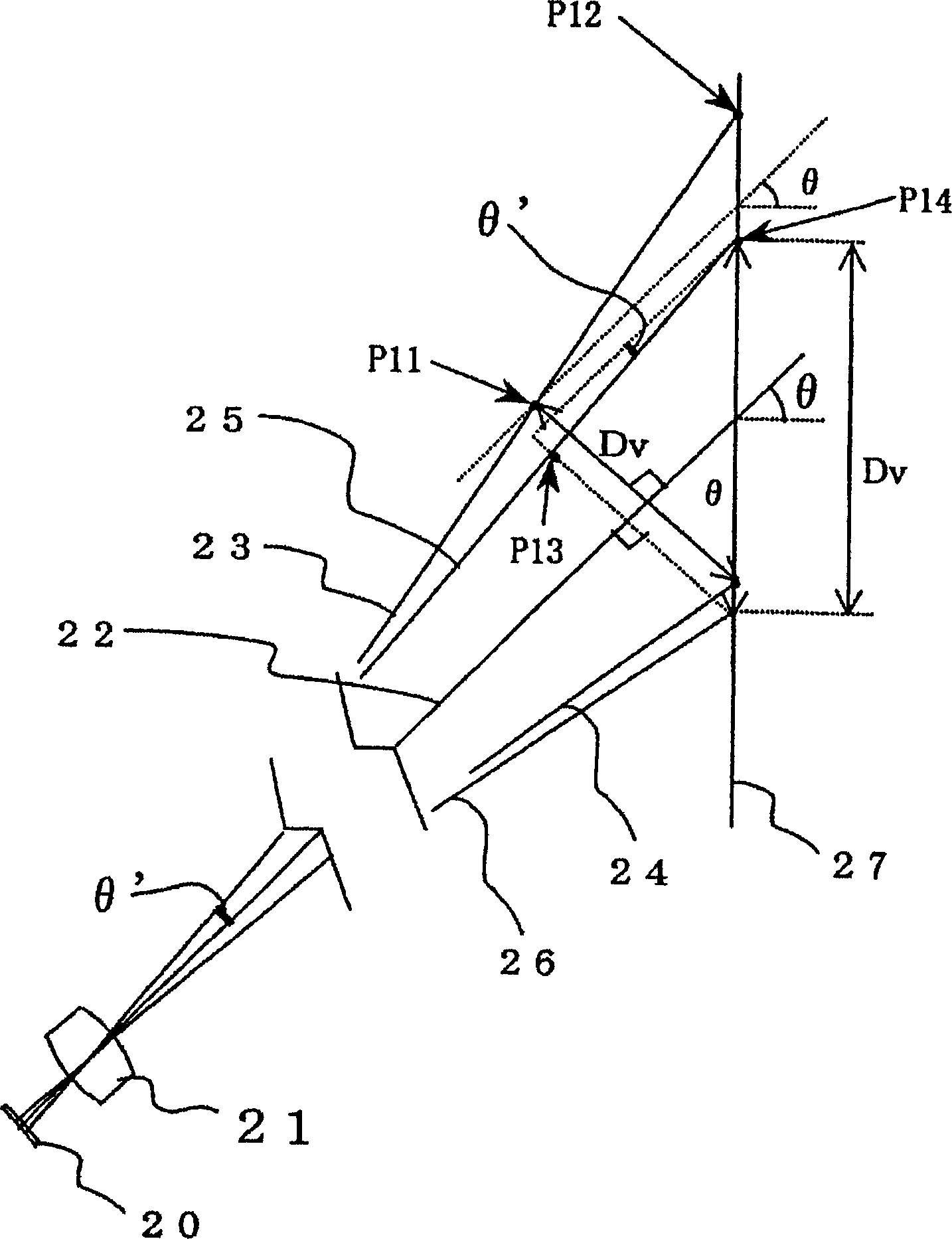
The present invention provides a projection image display device capable of suppressing trapezoidal distortion even when an image is obliquely enlarged and projected on a screen, and a projection optical unit used therefor. In the projection type image display device that enlarges the image on the image display element (1) through the projection lens (2), and displays the enlarged image by oblique projection relative to the screen (6), the projection lens (2) and the back mirror (5 ) are disposed between free-form surface mirrors (3, 4) having a free-form surface for correcting trapezoidal distortion produced by oblique projection of the enlarged image, and the surface shape is formed, and light rays placed at the upper end of the enlarged image are refracted by the free-form surface And the distance to the screen is L1, the light at the lower end of the enlarged image is refracted by the free-form surface and the distance to the screen is L2, and the distance from the upper end to the lower end of the picture on the screen is Dv, at least satisfy: |L1-L2 |>0.4·Dv.

Description

technical field [0001] The present invention relates to, for example, a projection image display device for displaying an image by projecting a color enlarged image on a screen, and more particularly to a projection image display device for projecting an enlarged image obliquely with respect to the screen so that the enlarged image can be obtained on the screen and a projection optical unit used therein. Background technique [0002] In a so-called projection type color image display device that enlarges and projects a color image on an image display element such as a projection type Braun tube or a liquid crystal display device (liquid crystal panel) on a screen through a projection optical unit, it is required to A sufficiently large enlarged image is obtained, and at the same time, the depth dimension of the device is shortened. In order to meet this requirement, in the prior art, it is known, for example, as described in JP-A-5-134213 A, JP-A No. 2000-162544 A, and JP-A ...

Claims


Application Information

Patent Timeline
Patent Type & Authority Applications(China)
IPC IPC(8): G02B27/18G02B13/18G02B13/24G03B21/00
Inventor 久田隆纪谷津雅彦平田浩二
Owner MAXELL HLDG LTD
Learn More