
Dark field detection device

A dark field detection and optical path technology, applied in measurement devices, optical testing flaws/defects, instruments, etc., can solve the problems of reducing the uniformity of the outgoing light, large difference in fiber energy, defect detection quality, etc., to improve lighting uniformity, The effect of line scan productivity improvement and uniform output light

Active Publication Date: 2022-06-28
SHANGHAI MICRO ELECTRONICS EQUIP (GRP) CO LTD
View PDF0 Cites 0 Cited by
  • Summary
  • Abstract
  • Description
  • Claims
  • Application Information

AI Technical Summary

Problems solved by technology

Because the annular dark field detection device in the prior art does not have a uniform light device, the energy difference of each optical fiber entering the annular dark field detection device is relatively large, which reduces the uniformity of the outgoing light of the annular dark field detection device, thus affecting the defect detection. quality

Method used


Image

  • Dark field detection device
  • Dark field detection device
  • Dark field detection device

Examples


Embodiment Construction

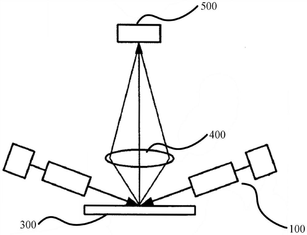
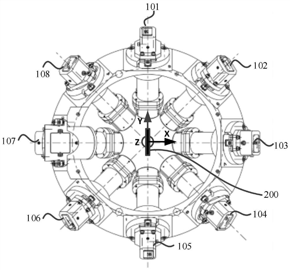
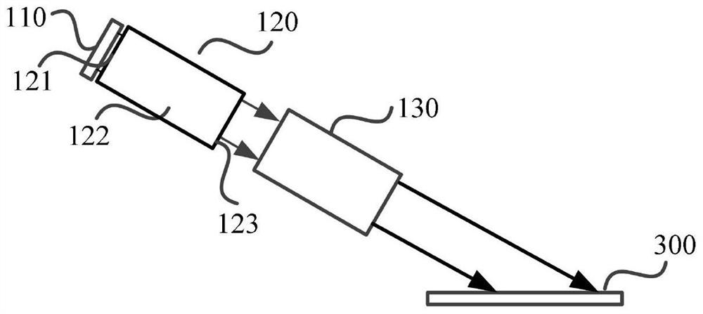
[0036] Attached to the following Figures 1 to 4 The dark field detection device proposed by the present invention will be further described in detail with reference to the specific embodiments. The advantages and features of the present invention will become more apparent from the following description. It should be noted that the accompanying drawings are in a very simplified form and all use inaccurate scales, and are only used to facilitate and clearly assist the purpose of explaining the embodiments of the present invention. For the purpose, features and advantages of the present invention to be more clearly understood, please refer to the accompanying drawings. It should be noted that the structures, proportions, sizes, etc. shown in the drawings in this specification are only used to cooperate with the contents disclosed in the specification, so as to be understood and read by those who are familiar with the technology, and are not used to limit the implementation of t...


PUM

PropertyMeasurementUnit
angle of incidenceaaaaaaaaaa
angleaaaaaaaaaa

Abstract

The invention provides a dark field detection device, which includes an illumination module, an optical path shaping module, an objective lens and an imaging sensor, and the optical path shaping module includes a plurality of overlapping linear illumination spots on a wafer. Branch light paths; each of the branch light paths is used to illuminate the wafer at a certain incident angle, and the plurality of branch light paths form a ring-shaped illumination; each of the branch light paths includes a uniform light structure and a critical illumination structure, and the The light provided by the light source is sequentially irradiated onto the wafer through the uniform light structure and the critical illumination structure. The invention can effectively improve the uniformity of illumination, and at the same time, it can also increase the illumination power density and suppress stray light, which is beneficial to the improvement of line scan productivity, avoids the granular distribution of illumination spots, and is more conducive to defects ( detection of particles, marked edges).

Description

technical field [0001] The invention relates to the technical field of semiconductor equipment, in particular to a dark field detection device. Background technique [0002] Dark field illumination technology is widely used in the field of instrument vision, such as the field of surface defect detection. Dark field illumination means that the illumination light is projected onto the surface of the sample at a very large incident angle. The reflected light is reflected at a very large reflection angle and cannot enter the objective lens for imaging; if there are defect features on the surface of the sample, part of the light diffusely reflected from the defect features can enter the objective lens for imaging, and these defect features appear as bright image contrasts In the dark field of view, it can finally be rendered in the CCD. The annular dark field detection device provides uniform illumination light for detecting defects such as depressions, protrusions, and scratche...

Claims


Application Information

Patent Timeline
Patent Type & Authority Patents(China)
IPC IPC(8): G01N21/88
CPCG01N21/8806G01N2021/8822
Inventor 李运锋李润芝王婷婷于大维
Owner SHANGHAI MICRO ELECTRONICS EQUIP (GRP) CO LTD
Learn More