Hollow metal pipe twisting formation method

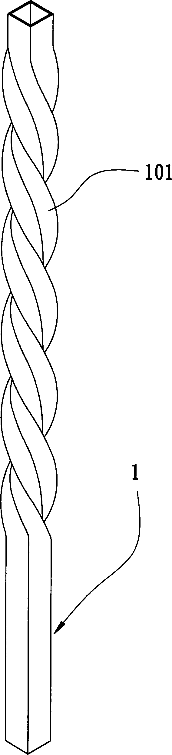
A molding method and metal tube technology, applied in the field of molding, can solve the problems of defective products, trouble, inconvenience of clamping and rotating the square tube 1, etc., and achieve the effect of reducing equipment cost and saving material cost.

Inactive Publication Date: 2006-05-17
钟 旻儒
View PDF0 Cites 10 Cited by
  • Summary
  • Abstract
  • Description
  • Claims
  • Application Information

AI Technical Summary

Problems solved by technology

[0004] 1. In order to maintain the pressure state of the support fluid 3 in the square tube 1, the pressure adjustment device 2 must be additionally installed on the square tube 1. This is not only troublesome, but also may cause the clamp to clamp and rotate the square tube 1. inconvenient
[0005] 2. This method is to use the support fluid 3 to fill the inside of the square pipe 1. Therefore, in order to maintain the pressure state

Method used


Image

  • Hollow metal pipe twisting formation method
  • Hollow metal pipe twisting formation method
  • Hollow metal pipe twisting formation method

Examples


Embodiment Construction

[0036] The aforementioned and other technical contents, features and effects of the present invention will be clearly understood in the following detailed description of the two preferred embodiments with reference to the accompanying drawings.

[0037] Before presenting a detailed description, it is noted that in the following description, similar elements are denoted by the same reference numerals.

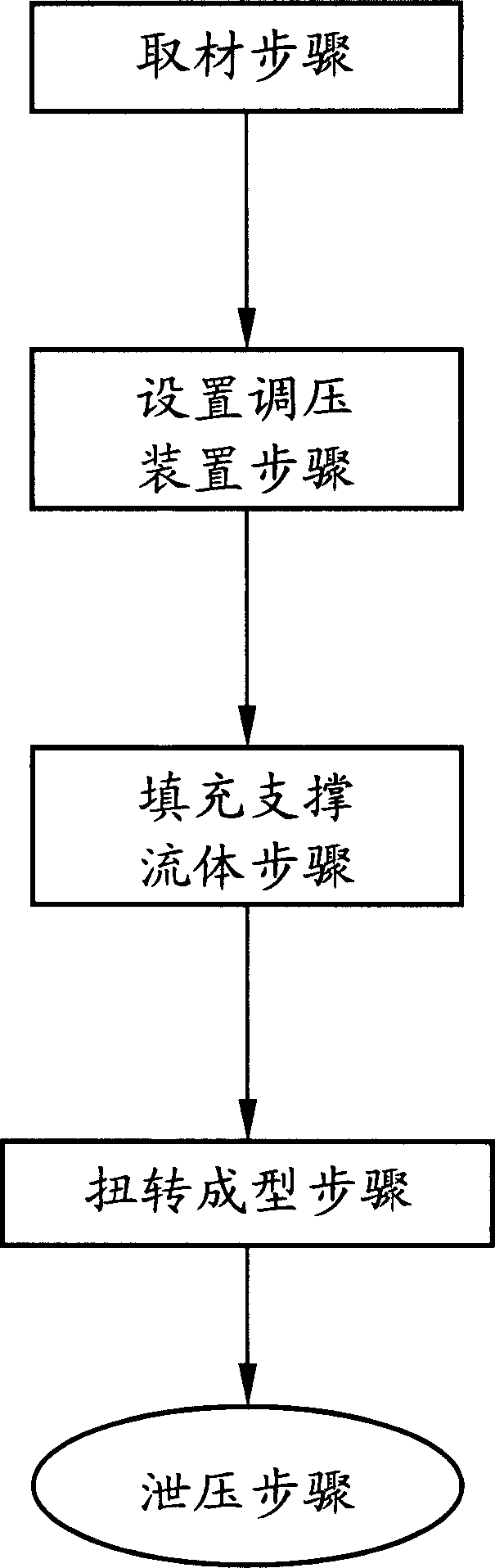
[0038] refer to Figure 4 , is the first preferred embodiment of the twist forming method of the hollow metal tube of the present invention, comprising the following steps:

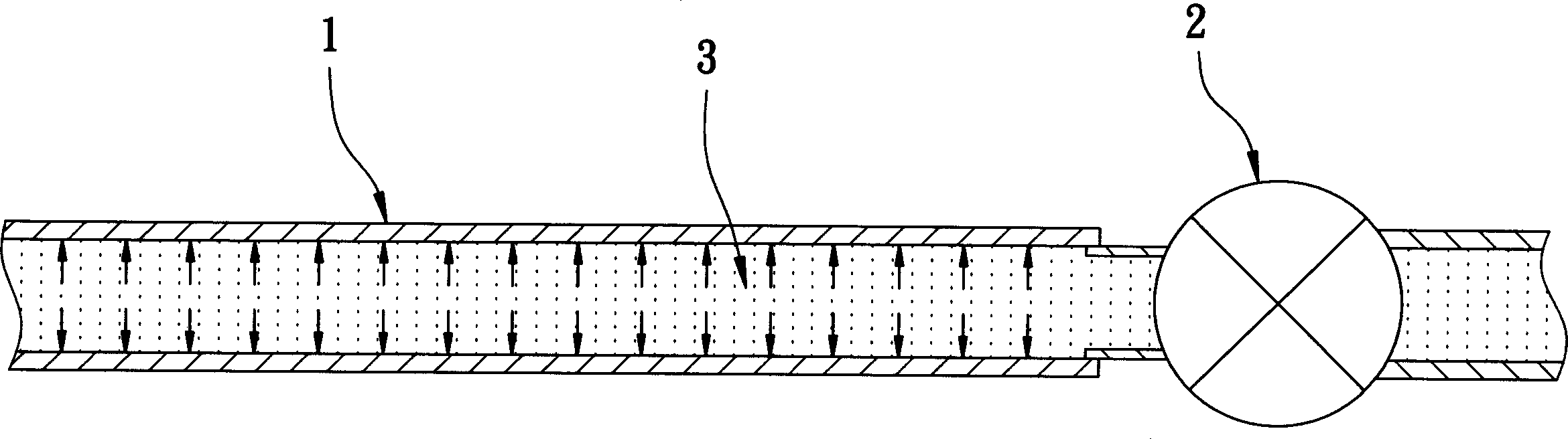
[0039] Step 1: Refer to Figure 5 , 6 , 7. Prepare a hollow metal tube 10 , a solid reinforcing piece 20 , and a twisting machine 30 . The metal pipe 10 has a first positioning section 11, a second positioning section 12, and a pre-torsion section 13 connected between the first and second positioning sections 11, 12 along an axis x, the first positioning section 11 has a first inner hole 111, the second...


PUM


Abstract

The metal pipe twisting formation process includes the following steps: A. preparing one metal pipe with one first locating section, one second locating section and one pre-twisted section in between, and one reinforcing part with cross section shape corresponding to that of the inner holes of the first locating section and the second locating section and length greater than that of the pre-twisted section; B. setting the reinforcing part inside the inner hole of the pre-twisted section with two ends of the reinforcing part stretched into the inner holes of the first locating section and the second locating section separately; and C. twisting the first locating section and the second locating section relatively to make the pre-twisted section form one twisting structure along the axis. The present invention has simple process, no influence on the support and rotation of fixture and no leakage.

Description

【Technical field】 [0001] The invention relates to a forming method, in particular to a hollow metal tube twist forming method with simple steps. 【Background technique】 [0002] Such as figure 1 , 2 , shown in 3, is the manufacturing method of existing a kind of hollow square pipe rotating structure, and its steps are: one, prepare a hollow square pipe 1; On an open end of the tube 1; 3. A support fluid 3 is filled in the square tube 1 through the pressure adjustment device 2, and the support fluid 3 in the square tube 1 is maintained at a high pressure by the pressure adjustment device 2 4. Clamp the square tube 21 at the predetermined position with a clamp (not shown in the figure), and rotate the clamp to force the square tube 21 to deform, and form a rotating structure 101 on the predetermined surface; and 5. Use the pressure adjusting device 2 to release the supporting fluid 3 in the square tube 1 . [0003] Although, in the above-mentioned manufacturing method, duri...

Claims


Application Information

Patent Timeline
IPC IPC(8): B21D11/14
Inventor 钟旻儒
Owner 钟 旻儒
Why Eureka
Try Eureka