

Low pressure storage high pressure transmission and supply cryogenic tank
A storage tank and low-temperature technology, which is applied in the field of cryogenic liquid storage and transportation equipment, can solve the problems of high manufacturing cost, poor cooling effect, and high material price of low-temperature storage tanks, and achieve the effects of saving equipment funds, good cooling effect, and thorough liquefaction
- Summary
- Abstract
- Description
- Claims
- Application Information
AI Technical Summary
Problems solved by technology
Method used
Image

Examples
Embodiment Construction
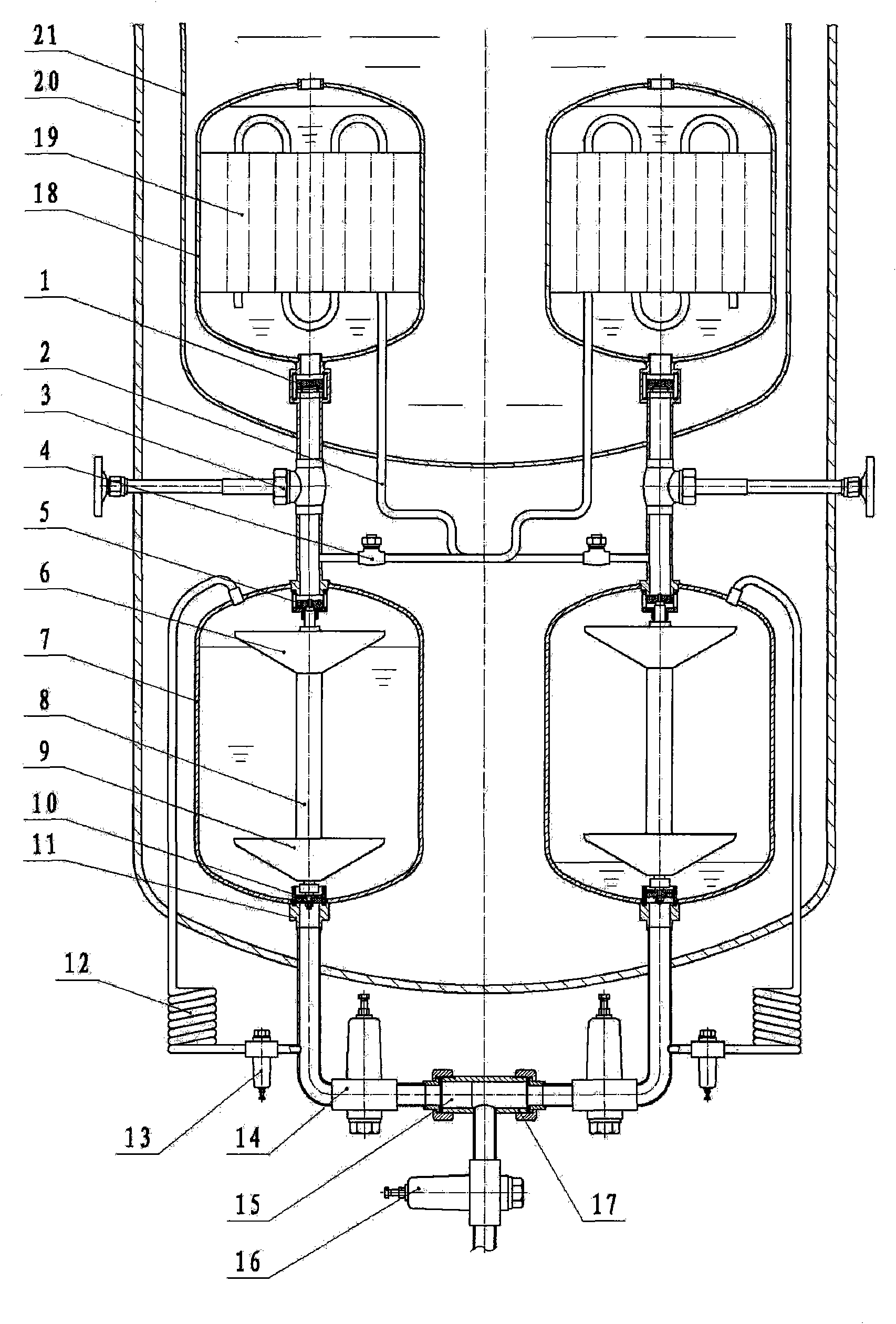
[0007] With reference to accompanying drawing, it comprises low-temperature storage tank 20, and low-temperature storage tank liner 21 is arranged in the low-temperature storage tank, and two condensation tanks 18 with completely identical structure are arranged in the low-temperature storage tank liner 21, and the low-temperature storage tank liner 21 below There are two booster tanks 7 with exactly the same structure in the cryogenic storage tank, and the outlet valve 1 at the bottom of each condensation tank passes through the main valve 3 of the booster tank below it and the inlet valve of the booster tank at the top of the booster tank 7 below it. 5 are connected; the condensation tank is equipped with a condenser 19, and there is a pressure relief pipe 2 between the main valve 3 of the booster tank and the inlet valve 5 of the booster tank, and there is a check valve 4 on the pressure relief pipe. The pressure pipes are all connected to the condenser in the condensation t...
PUM
 Abstract
Description
Claims
Application Information