
Coated conductor high temperature superconductor carrying high critical current under magnetic field by intrinsic pinning centers, and methods of manufacture of same

a high-temperature superconductor, intrinsic pinning center technology, applied in the direction of superconductors/hyperconductors, superconductors, electrical equipment, etc., can solve the problems of high cost, high critical current density, high cost, etc., and achieve high critical current density, high critical current, and high critical current density

Active Publication Date: 2018-01-11
HIGH TEMPERATURE SUPERCONDUCTORS INC
View PDF4 Cites 0 Cited by
  • Summary
  • Abstract
  • Description
  • Claims
  • Application Information

AI Technical Summary

Benefits of technology

This solution achieves high critical current density and current-carrying capacity in high magnetic fields, reducing costs and process complexity, making it suitable for industrial applications such as power transmission and wind turbine generators.

Problems solved by technology

Early efforts, sometimes termed the first generation (1G) HTS, to form wires did not yield technically or commercially acceptable solutions.
Unfortunately, the HTS was too brittle and costly due to high silver content for the intended applications.
Adding these extrinsic elements to (RE)BCO makes the process more complicated and also raises cost.
Another approach which has proved less promising to date is introducing microstructural defects, into the HTS.
Other investigators have reported on process dependent limitations, such as critical current saturation as a function of film thickness, for coated conductors formed via pulsed laser deposition.

Method used


Image

  • Coated conductor high temperature superconductor carrying high critical current under magnetic field by intrinsic pinning centers, and methods of manufacture of same
  • Coated conductor high temperature superconductor carrying high critical current under magnetic field by intrinsic pinning centers, and methods of manufacture of same
  • Coated conductor high temperature superconductor carrying high critical current under magnetic field by intrinsic pinning centers, and methods of manufacture of same

Examples


Embodiment Construction

Definitions

[0052]“ReBaCuO superconductor” means tare earth (Re), barium (Ba), copper (Cu) and oxygen (O) containing compositions that constitute superconductors at cryogenic temperatures.

[0053]“Substantially pure ReBaCuO superconductor” means a ReBaCuO superconductor that contains less than 2%, preferably less than 1%, most preferably less than 0.5% by weight of materials other than Re, Ba, Cu and O.

Structure and Process

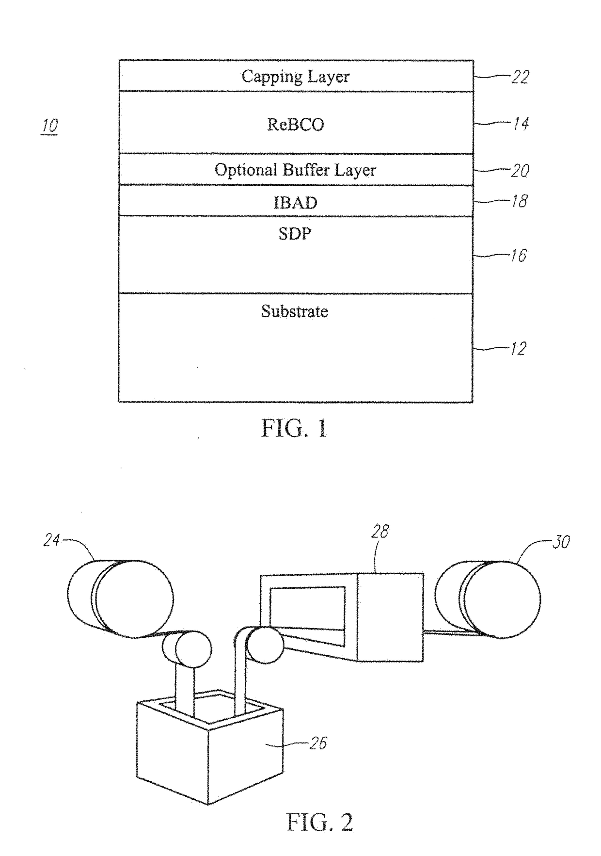
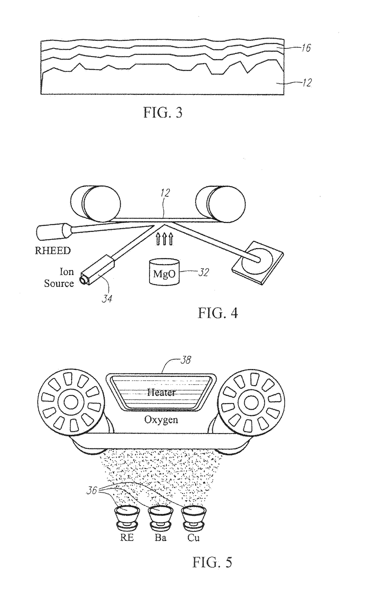
[0054]FIG. 1 shows a cross-section of one embodiment of the coated conductor 10. At least a substrate 12 and (RE)BCO layer 14 are provided. The substrate 12 supports, either directly or through the presence of one or more intermediate layers, the (RE)BCO(RE)BCO layer 14. Optionally, a solution deposition planarization layer 16 is formed at the surface of the substrate 12. The solution deposition planarization layer 16 may then directly support the (RE)BCO layer 14, or may interface with an intermediate layer 18. In one implementation, the intermediate layer 18 may be...


PUM

PropertyMeasurementUnit
widthaaaaaaaaaa
widthaaaaaaaaaa
widthaaaaaaaaaa

Abstract

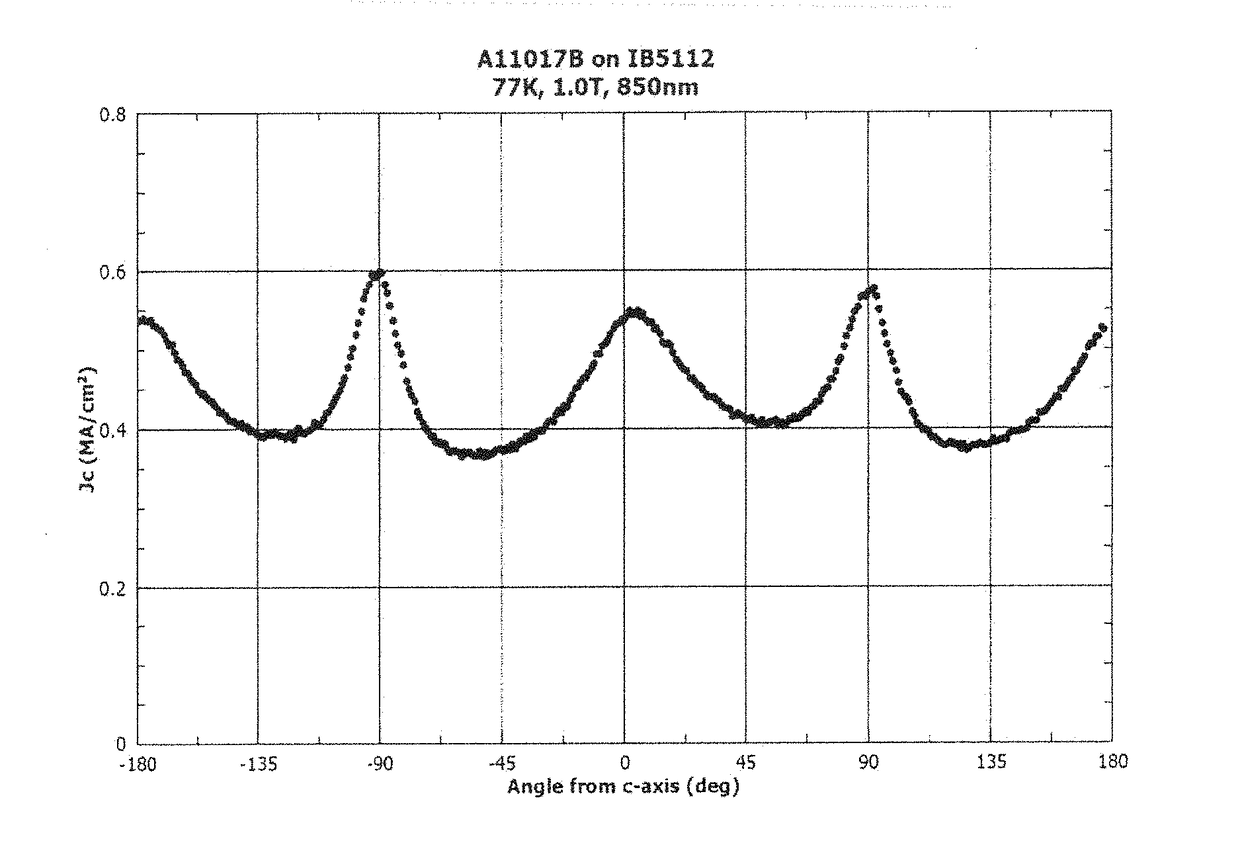
A coated conductor comprises a substrate supporting a ReBCO superconductor adapted to carry current in a superconducting state. The superconductor is characterized in having peaks in critical current (Jc) of at least 0.2 MA / cm2 in a magnetic field of about 1 Tesla when the field is applied normal to the surface of the superconductor and when the field is applied parallel to the surface of the superconductor, and further characterized in that the superconductor includes horizontal defects and columnar detects in a size and an amount sufficient to result in the said critical current response. The conductor is characterized in that the ratio of the height of the peaks in the Jc is in the range from 3:1 with the ratio of the field perpendicular (0 degrees) to the field parallel (+ / −90 degrees) to the range from 3:1 with the ratio of the field parallel to the field perpendicular.

Description

PRIORITY CLAIM[0001]This application is a continuation of application Ser. No. 14 / 047,672, filed Oct. 7, 2013 (our Reference 844,004-415); which is a continuation-in-part of application Ser. No. 13 / 369,186 filed Feb. 8, 2012, now U.S. Pat. No. 9,362,025 (our Reference 844,004-412), which are hereby incorporated by reference as if fully set forth herein.FIELD OF THE INVENTION[0002]The present invention relates to coated conductor high temperature superconductor (HTS) conductors having high in-field current and current carrying capacity. More particularly, the coated conductors are formed as superconducting wires.[0003]While no claims of priority are being made to the following cases, they include relevant subject matter: Ruby, et al., “High-Throughput Deposition System for Oxide Thin Film Growth By Reactive Coevaporation”, now published as US Published Application 2007 / 0125303 and Moeckly et al., “RF-Properties Optimized Compositions of (RE)Ba2Cu3O7-δ Thin Film Superconductors”, now ...

Claims


Application Information

Patent Timeline
Patent Type & Authority Applications(United States)
IPC IPC(8): H01B12/06H01L39/12H01L39/14H01L39/24H10N60/00H10N60/01H10N60/20H10N60/85
CPCH01L39/2461H01L39/2458H01B12/06H01L39/143H01L39/126H01L39/2432H10N60/203H10N60/857H10N60/0381H10N60/0604H10N60/0632
Inventor HUH, JEONG-UK
Owner HIGH TEMPERATURE SUPERCONDUCTORS INC
Learn More