
Colour display device

A display and color technology, used in color TVs, static indicators, and components of color TVs, etc., can solve problems such as inability to adjust, drop in screen resolution, and color deviation, and achieve a smooth and soft screen.

Inactive Publication Date: 2006-05-17
INNOLUX CORP
View PDF3 Cites 24 Cited by
  • Summary
  • Abstract
  • Description
  • Claims
  • Application Information

AI Technical Summary

Problems solved by technology

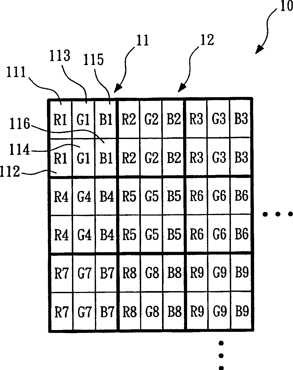
[0004] 1. Kalluri (US5,711,474) proposes to divide a pixel into multiple areas with different characteristics to meet the display under different viewing angles. The disadvantage is that it cannot be adjusted once it is manufactured, and different areas correspond to specific different areas. Display angle, the display effect of the original picture will be reduced
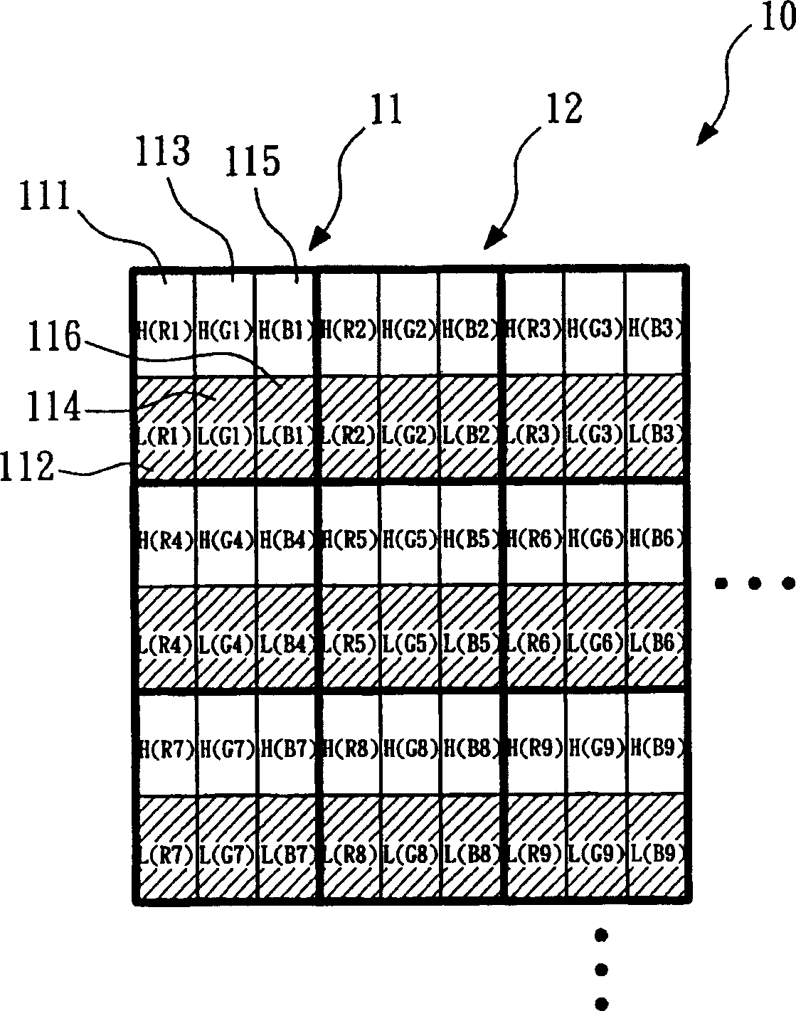
[0005] 2. Susumu (US5,847,688) proposed to use the original signal according to the characteristic curve (Gamma Curve) of two different viewing angles, and input it through different drivers (driver) at each two screen times. The disadvantage is that the screen is in two The change within a picture time will cause the picture to flicker, and only half of the pixels of the synthesized picture are displayed for the picture at a specific angle, which cannot actually solve most viewing situations, and will cause a decrease in picture resolution
[0006] 3. Paul et al. (US2002 / 0149598) proposed to use more than 2×2 sub-pixels (subpixel) to display the screen, use the calculated value to adjust the original display screen, and use different ratios of bright and dark pixel (pixel) ratios to complete Display, the disadvantage is that it uses multiple pixels (pixels) for display operations, and considers each pixel (pixel) as a unit, so it is necessary to solve the problem of color deviation when the resolution is greater than 170dpi
Therefore, it may cause uneven brightness and darkness on the screen, which may cause visually undesirable effects.

Method used


Image

  • Colour display device
  • Colour display device
  • Colour display device

Examples


Embodiment Construction

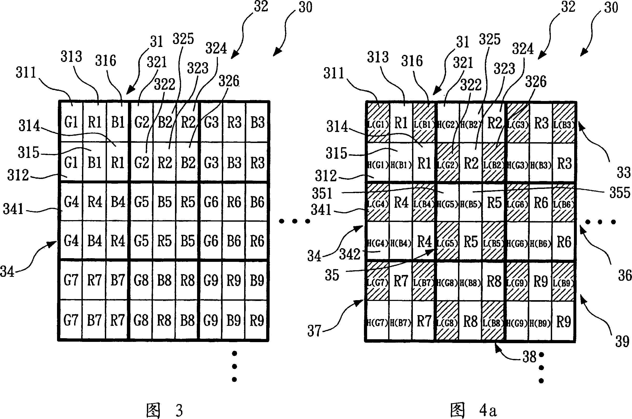
[0097] Referring to FIG. 3 , a color display 30 according to the first embodiment of the present invention includes: a plurality of pixels 31 , 32 and so on. The plurality of pixels 31 and 32 are arranged in a matrix, and each pixel includes a first color pixel, a second color pixel and a third color pixel. Taking the first pixel 31 as an example, the first color pixel is a green pixel, the second color pixel is a red pixel, and the third color pixel is a blue pixel. The green pixel has a first green sub-pixel 311 and a second green sub-pixel 312 . The red pixel has a third red sub-pixel 313 and a fourth red sub-pixel 314 . The blue pixel has a fifth blue sub-pixel 315 and a sixth blue sub-pixel 316 .

[0098] The first green sub-pixel 311 is adjacent to the second green sub-pixel 312 and is disposed in the first column of the first pixel 31 . The third red sub-pixel 313 is adjacent to the fifth blue sub-pixel 315 and is located in the second column of the first pixel 31 . ...


PUM


Abstract

A color display consists of multiple first pixel including tree colored pixels with each having at least two sub pixels to the first pixel in the first arrangement mode as well as multiple second pixel being cross ¿C set along a coordinate axial direction to multiple the first pixel and including three colored pixels with each having at least two sub pixels to the second pixel in the second arrangement mode. It features that two arrangement modes are not the same, multiple sup pixels are used to coordinate to display signal driving of bright ¿C dark state so as to solve phenomenon of bright ¿C dark unevenness on picture.

Description

technical field [0001] The invention relates to a color display. Background technique [0002] Generally speaking, since the light transmittance of a front-view liquid crystal display is not the same as that of a side-view liquid crystal display, this is because the incident light of different angles in the liquid crystal layer produces different phase difference values ​​(Retardation), so when When the viewing angle is different, the deflection coefficient of the light is different, resulting in a different transmittance. Therefore, different viewing angles will cause different brightness of the displayed light. And when different color lights (such as red light, green light and blue light) are mixed with different brightness ratios when viewed from the front and viewed from the side, there will be a color shift phenomenon in which the displayed colors are different when viewed from the front and viewed from the side. How to reduce the color deviation when the liquid crys...

Claims


Application Information

Patent Timeline
Patent Type & Authority Applications(China)
IPC IPC(8): G09G3/36G02F1/133H04N5/66
Inventor 石明家许英豪
Owner INNOLUX CORP
Learn More