Heat exchanger

A heat exchanger and heat exchanger tube technology, applied in heat exchange equipment, lighting and heating equipment, tubular elements, etc., can solve the problems of small rib coefficient, poor heat exchange performance, small heat transfer area, etc. The effect of large rib coefficient, ingenious design and large heat transfer area

Inactive Publication Date: 2006-05-24
GUANGDONG MIDEA ELECTRIC APPLIANCES CO LTD
View PDF0 Cites 7 Cited by
  • Summary
  • Abstract
  • Description
  • Claims
  • Application Information

AI Technical Summary

Problems solved by technology

[0002] The heat exchangers used in existing refrigeration and air-conditioning equipment use different forms of fins. Although their air-side heat transfer coefficients and resistance characteristics are different, their common disadvantages are that the heat transfer area is small and the finning coefficient is relatively small. Small, poor heat exchange performance

Method used


Image

  • Heat exchanger
  • Heat exchanger
  • Heat exchanger

Examples


Embodiment

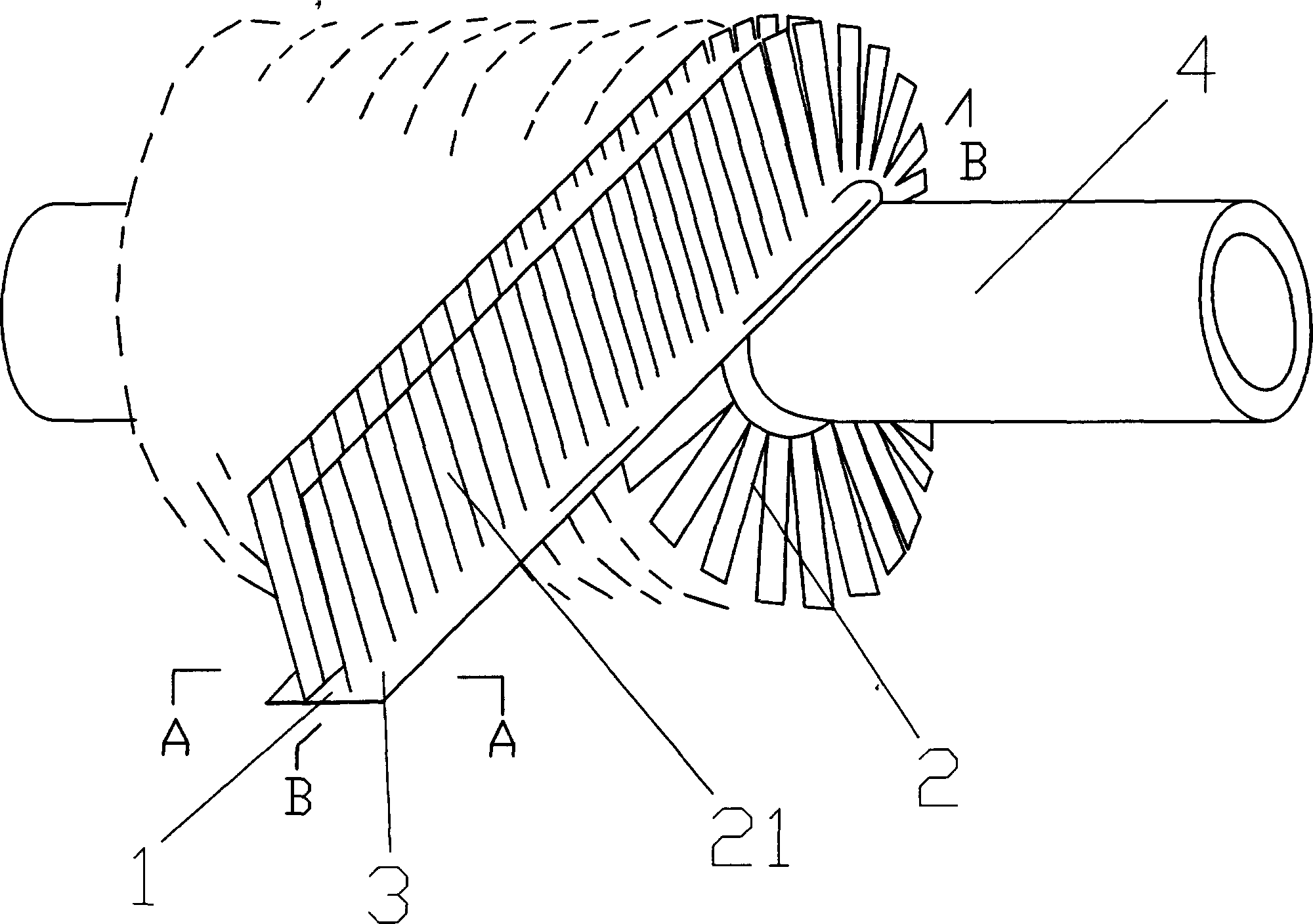
[0014] The structure diagram of the present invention is as figure 1 As shown, it includes a heat exchanger tube 4 and fins 2 arranged on the heat exchanger tube 4 , wherein the fin 2 is a strip-shaped fin fixed on the outer surface of the heat exchanger tube 4 in a spiral shape.

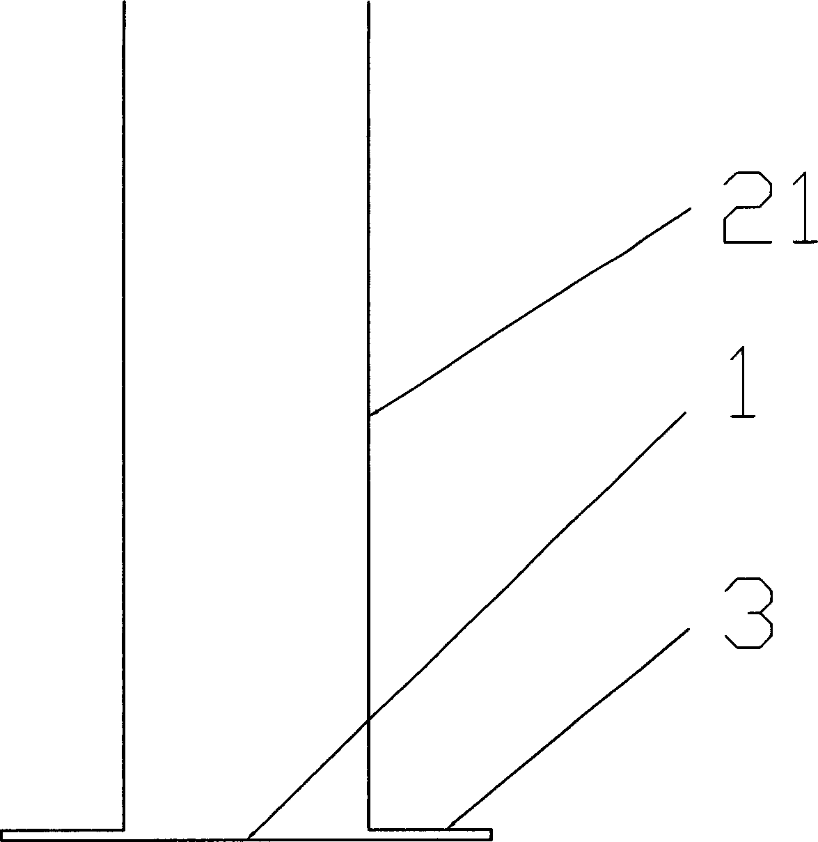
[0015] For ease of installation, the above-mentioned strip fins 2 include a substrate 1 and a plurality of fins 21. The plurality of fins 21 are erected and fixed on the substrate 1, and then spirally wound on the heat exchanger tube 4 through the substrate 1. .

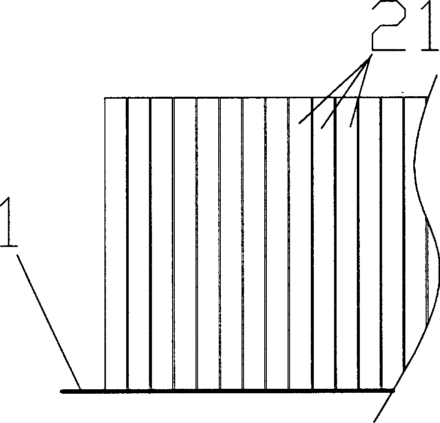
[0016] In order to ensure the uniformity of heat exchange in the present invention, the plurality of fins 21 are fixed on the substrate 1 at equal intervals along the circumferential direction.

[0017] In order to further increase the installation speed, thereby improving the productivity of the present invention, the substrate 1 is fixed with several rows of fins 21 arranged at equal intervals in the axial direction, such as two or thre...


PUM


Abstract

The heat exchanger includes pipes of heat exchanger and fins on pipes. Fins on bars arranged in helical shape are setup on excircle surface of pipe. Bar shaped fins includes basal pieces and fins. Fins are vertically installed on basal pieces. Basal pieces enwinds on pipes of heat exchanger in helical shape. Features are: large heat transfer surface area, large rib coefficient and good performance of heat exchange. Features are: smart design, new and reasonable structure

Description

1. Technical field: [0001] The invention relates to a heat exchanger used in refrigeration and air-conditioning equipment, which belongs to the transformation technology of the heat exchanger. 2. Background technology: [0002] The heat exchangers used in existing refrigeration and air-conditioning equipment use different forms of fins. Although their air-side heat transfer coefficients and resistance characteristics are different, their common disadvantages are that the heat transfer area is small and the finning coefficient is relatively small. Small, poor heat exchange performance. 3. Contents of the invention: [0003] The object of the present invention is to provide a heat exchanger with large heat transfer area, large ribbing coefficient and good heat exchange performance in consideration of the above problems. [0004] The structure diagram of the present invention is as figure 1 As shown, it includes heat exchanger tubes (4) and fins (2) arranged on the heat exc...

Claims


Application Information

Patent Timeline
Patent Type & Authority Applications(China)
IPC IPC(8): F28F1/36
Inventor 董剀军黄灿彬
Owner GUANGDONG MIDEA ELECTRIC APPLIANCES CO LTD
Why Eureka
Try Eureka