
Light emitting device and method for detecting part of detecting flat panel display detection unit

A flat-panel display and testing device technology, which can be used in the testing of machine/structural components, measuring devices, optical instrument testing, etc., and can solve problems such as difficulties

Inactive Publication Date: 2006-06-07
PHICOM CORP
View PDF0 Cites 13 Cited by
  • Summary
  • Abstract
  • Description
  • Claims
  • Application Information

AI Technical Summary

Problems solved by technology

[0019] In addition, whenever the imaging device 70 is repaired or replaced, the difficult task of resetting the position of the imaging device 70 is required.
Since the photographing device 70 is fixedly installed on the top surface of the substrate 30, it is difficult to apply the photographing device 70 to flat panel display panels 60 of various sizes.

Method used


Image

  • Light emitting device and method for detecting part of detecting flat panel display detection unit
  • Light emitting device and method for detecting part of detecting flat panel display detection unit
  • Light emitting device and method for detecting part of detecting flat panel display detection unit

Examples


Embodiment Construction

[0043] The present invention will be described more fully hereinafter with reference to the accompanying drawings, in which preferred embodiments of the invention are shown.

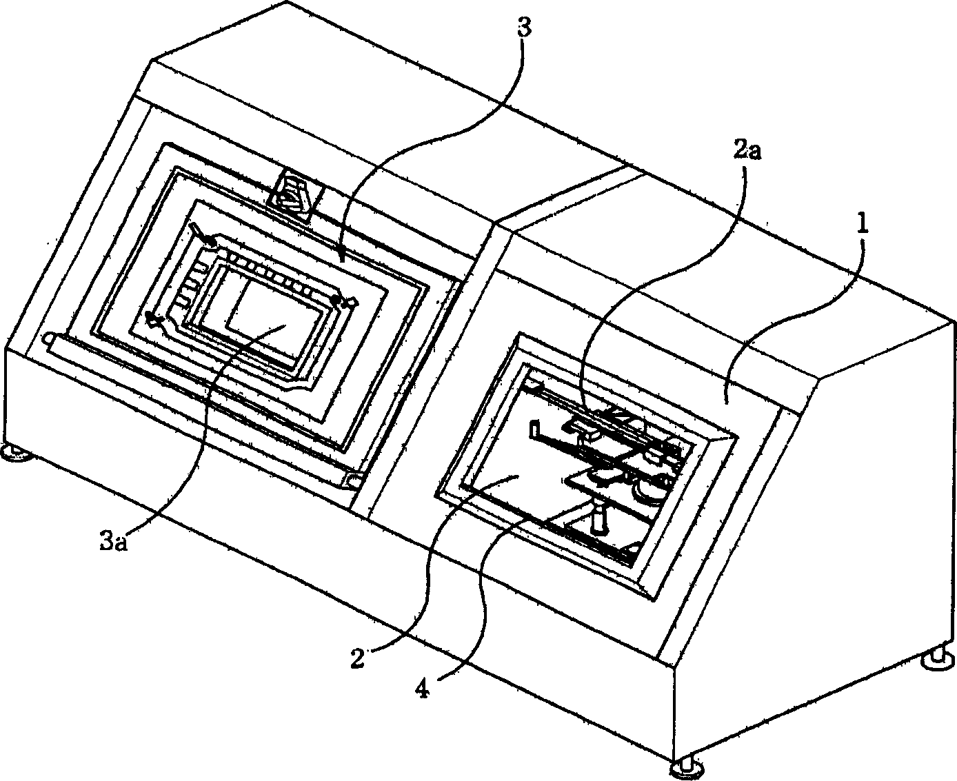
[0044] Figure 4 is a perspective view of a flat panel display test unit according to the present invention. The flat panel display testing unit includes a testing unit body 6, a flat panel conveying device 7 placed in the testing unit body 6, a sub-table 7a included in the flat panel conveying device 7 for receiving the supplied flat panel display panels, A conveying device (not shown) for the flat panel display panel received by the work table 7a, a work table 8a for receiving the flat panel display panel conveyed by the above-mentioned conveying device, and a test for testing the flat panel display panel placed on the work table 8a part.

[0045] The test section 8 includes a light emission test device for testing the flat panel display panel according to the size of the flat panel display panel. T...


PUM


Abstract

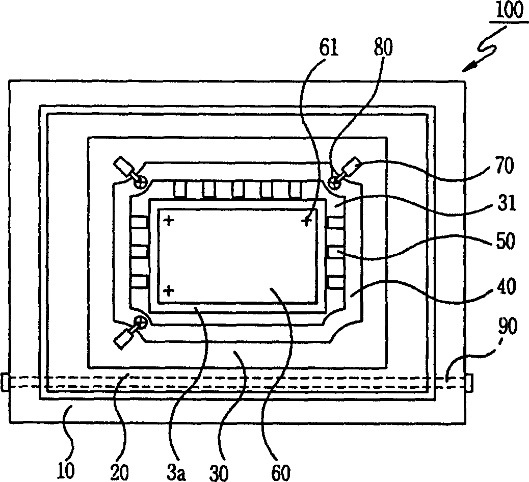
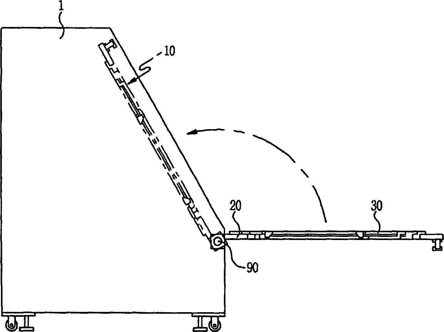
The present invention provides lighting test apparatus and method of a test part of a flat panel display test unit for testing a lighting state of a flat display panel transferred from a panel supply part on a worktable. The lighting test apparatus includes a lighting test body being a square-shaped plate in which an opening is formed; a first plate installed at one side of the lighting test body; a second plate movably installed at a side of the lighting test body adjacent to the first plate; one or more sub-plates attachably / removably coupled with the first and second plates and successively coupled toward the center of the opening of the lighting test body according to a size of the flat display panel; a probe plate attachably / removably coupled with the first plate, the second plate or a subplate which is nearest from the center of the opening of the lighting test body, wherein a plurality of probes are installed at the probe plate; and position setting means for aligning an align mark on the flat display panel with a virtual reference mark to set a reference coordinate value of the worktable.

Description

technical field [0001] The present invention relates to a luminescence test device and a luminescence test method of a test portion of a flat panel display test unit. Background technique [0002] It is well known to use glass substrates in the manufacture of flat panel displays such as thin film transistor liquid crystal displays (TFT-LCDs), plasma display panels (PDPs) and organic light emitting displays (OLEDs). In recent years, there has been a trend toward larger and thinner glass substrates (for example, 1,100 mm long, 1,250 mm wide, and 0.5-1 mm thick). Flat panel displays manufactured using glass substrates require luminescence testing during the final manufacturing process. In order to realize the luminescence test, it is necessary to perform an open circuit test and a color test on each data line and each gate line (gate line) of the flat panel display using a probe. In addition, visual inspection using a microscope or the like is also necessary. [0003] figur...

Claims


Application Information

Patent Timeline
IPC IPC(8): G01R31/00H01J11/20G01M11/00H01J9/42
CPCG01R31/24G02F1/136254H01J9/42H01J11/20
Inventor 金泰秀
Owner PHICOM CORP
Learn More