
Golf club head

A golf club head and club head technology, applied to golf balls, golf clubs, rackets, etc., can solve the problems of insufficient flight distance and poor hitting feeling, and achieve improved flight distance, improved hitting feeling, and good The effect of hitting the ball

Inactive Publication Date: 2006-06-21
BRIDGESTONE SPORTS CO LTD
View PDF1 Cites 0 Cited by
  • Summary
  • Abstract
  • Description
  • Claims
  • Application Information

AI Technical Summary

Problems solved by technology

[0005] However, if Figure 4 , Figure 5 As shown, due to the above-mentioned deep center of gravity of the club head, the center of gravity position A of the club head on the ball striking surface is higher than the centroid position B of the face part, and when the golf ball is hit with the face part 16, the face part 16 cannot fully Bending, not only the flying distance is not enough, but also the feeling of hitting the ball will deteriorate

Method used


Image

  • Golf club head
  • Golf club head
  • Golf club head

Examples


Embodiment 1

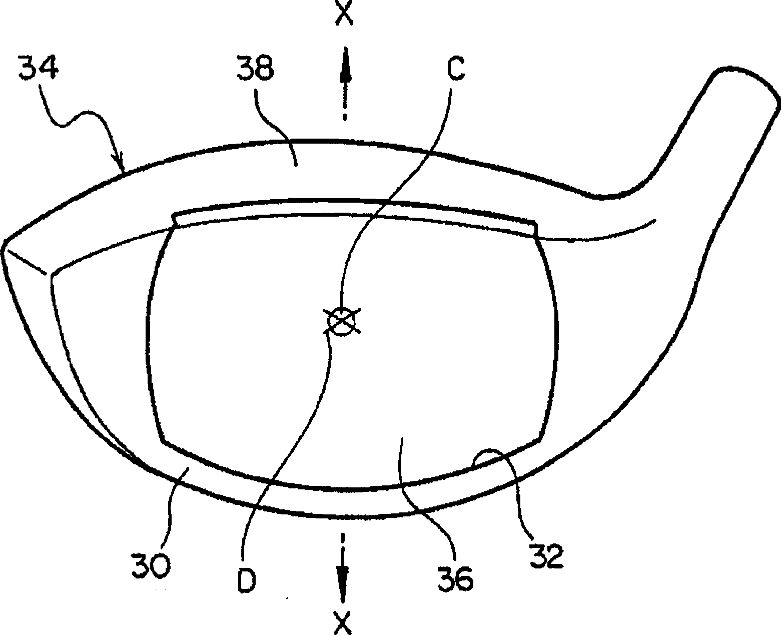
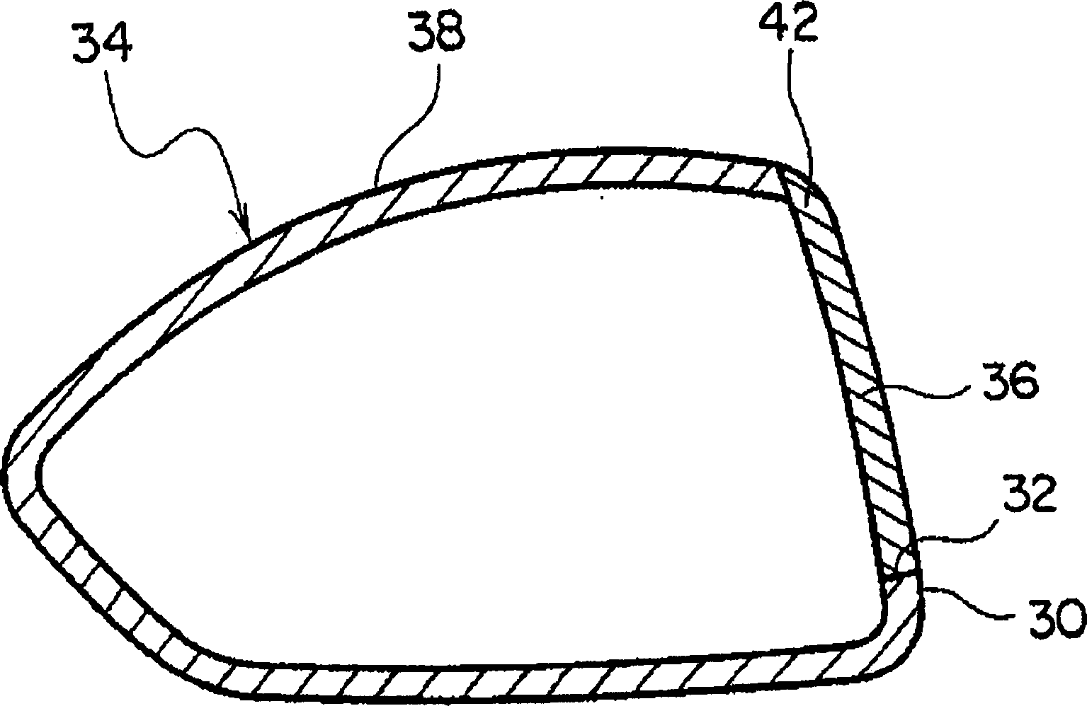
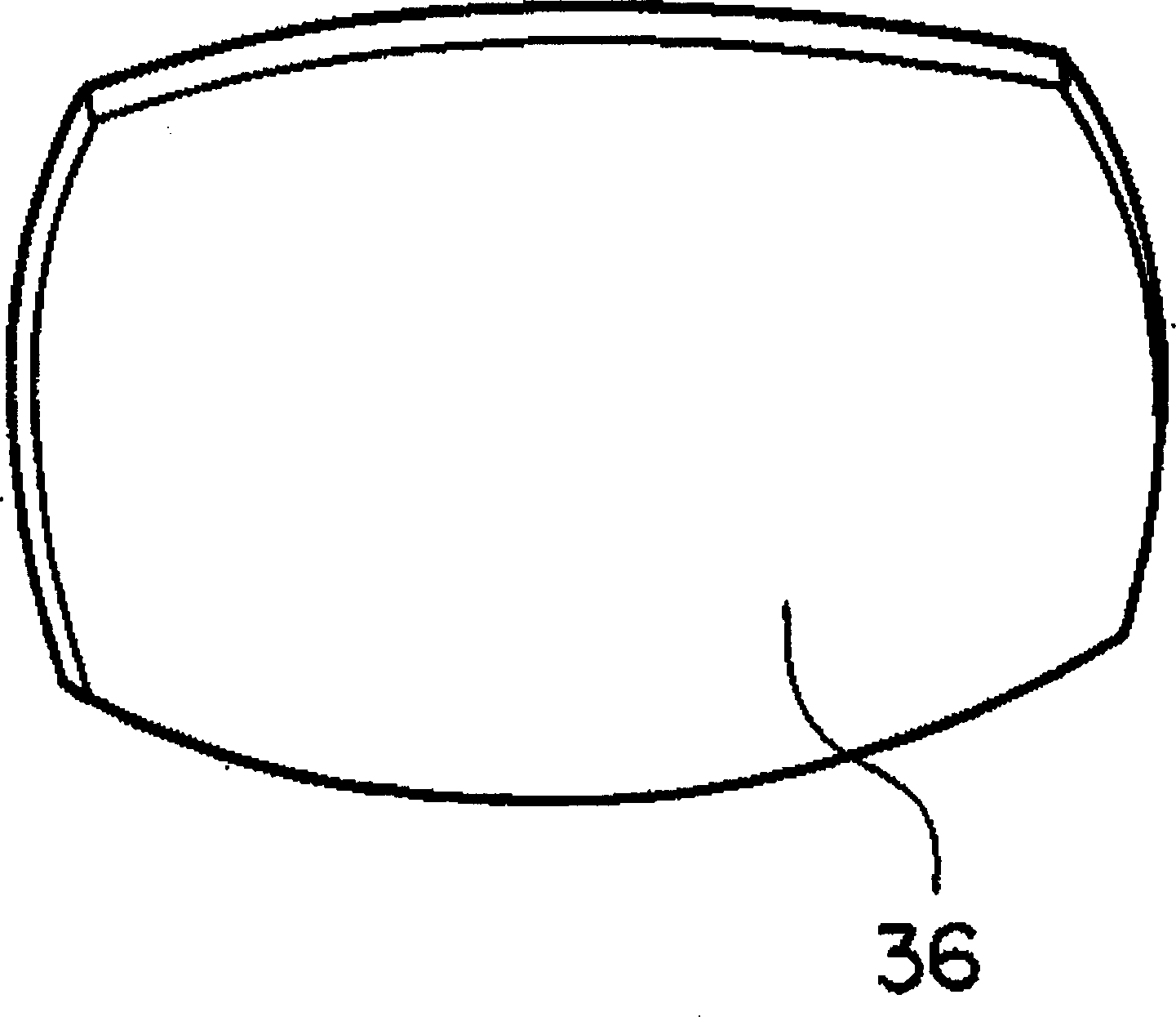
[0029] Such as Figure 1-Figure 3 In the golf club head of the above-mentioned embodiment shown, the position of the center of gravity of the club head on the ball striking surface coincides with the position of the centroid of the face member. 3.8 mm above the center position of the vertical direction of the spherical surface.

Embodiment 2

[0031] Such as Figure 1-Figure 3 In the golf club head of the above-mentioned embodiment shown, the position of the center of gravity of the club head on the ball striking surface coincides with the position of the centroid of the face member. 3.7mm above the center position of the vertical direction of the spherical surface.


PUM


Abstract

The present invention provides a golf club head in which the face part is sufficiently bent when hitting a golf ball with the face part, thereby improving the flight distance and the hitting feeling. The hollow golf club head of the present invention has a head body (34) and a face member (36), the head body (34) has a face opening (32) on the ball striking surface (30), and the face member (36) For filling the face opening, part or all of the upper edge of the face opening and the upper edge of the face member extends to the crown (38).

Description

technical field [0001] This invention relates to hollow golf club heads. Background technique [0002] In the past, hollow golf club heads have the following structures, such as Figure 4 , Figure 5 As shown, it has a club head body 14 having a face opening 12 on its ball striking face 10 and a face member 16 for filling the face opening 12 (for example, see Japanese Patent Laid-Open Publication No. 2001-137396). [0003] The above-mentioned hollow golf club heads, especially the recent hollow golf club heads made of titanium alloy, can be made larger due to the improvement of manufacturing technology. In addition, not only the enlargement of the club head, but also research is progressing to improve the ease of return and pilling of the club head at the time of impact by deepening the center of gravity of the club head. [0004] Such as Figure 4 , Figure 5 As shown in the hollow golf club head, when the position of the center of gravity of the club head on the hittin...

Claims


Application Information

Patent Timeline
Patent Type & Authority Applications(China)
IPC IPC(8): A63B53/04A63B102/32
CPCA63B53/0466A63B2209/00A63B53/0416A63B53/04
Inventor 今本泰范山岸久松永英夫
Owner BRIDGESTONE SPORTS CO LTD
Learn More