
Electric connector

A technology for electrical connectors and circuit boards, which is used in connection, fixed connection, circuit, etc., can solve the problems of complex structure of locking elements, difficulty in stamping and forming, and increase in production cost, and achieves improved utilization, good processability, Avoid the effect of bending too much

Inactive Publication Date: 2006-06-21
FOXCONN (KUNSHAN) COMPUTER CONNECTOR CO LTD +1
View PDF1 Cites 6 Cited by
  • Summary
  • Abstract
  • Description
  • Claims
  • Application Information

AI Technical Summary

Problems solved by technology

This kind of locking mechanism can well realize the buckling function of the electronic card, and has the advantages of good elasticity and can hold the connector at the same time. However, according to the space requirements on the circuit board, the height of the card edge connectors varies in practical applications. Similarly, when the heights of the connectors are different, all the locking elements with the holding function locking mechanism must be replaced, which increases the production cost. In addition, the configuration of the locking elements with the holding function locking device has a large number of bends, which As a result, the locking element has disadvantages such as complex structure, difficult stamping and forming, and high manufacturing cost

Method used


Image

  • Electric connector
  • Electric connector
  • Electric connector

Examples


Embodiment Construction

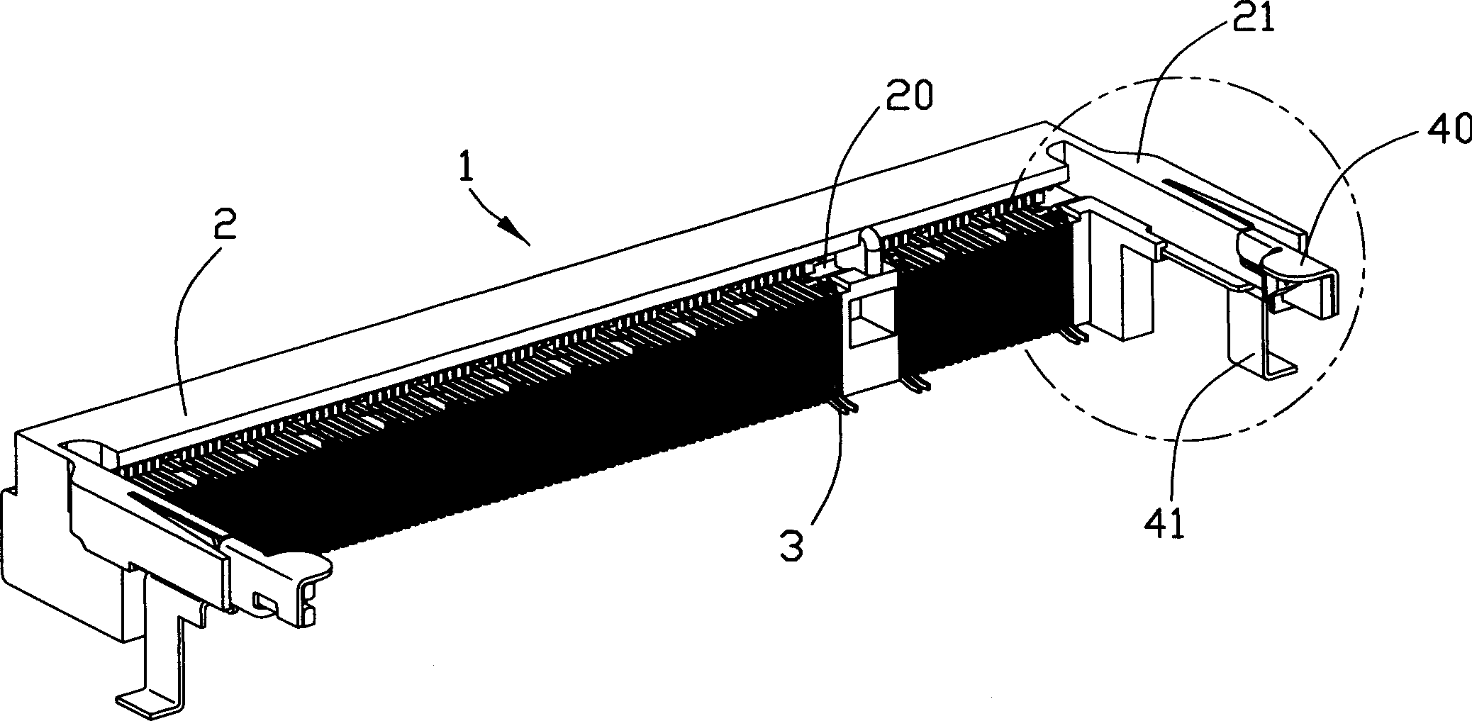
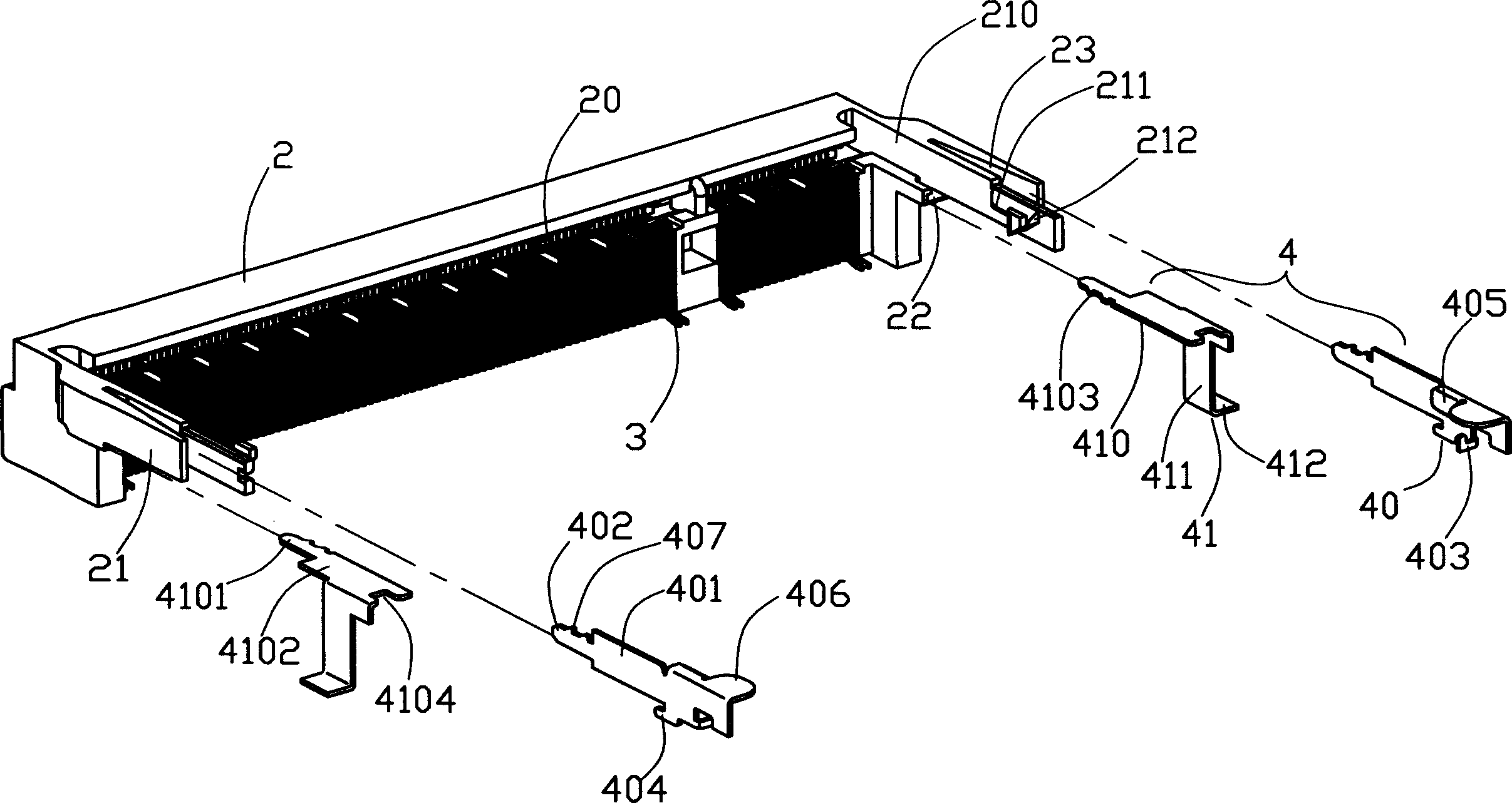
[0013] see figure 1 and image 3 As shown, the electrical connector 1 of the present invention includes an insulating body 2, a plurality of conductive terminals 3 accommodated in the insulating body 2, and a pair of locking mechanisms 4 positioned at opposite ends of the insulating body. .

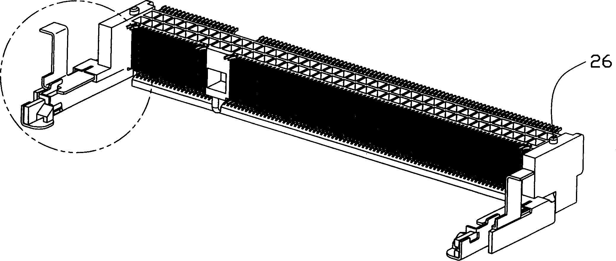
[0014] see image 3 , Figure 4 and Figure 6 As shown, the insulating body 2 is provided with a slot 20 along its longitudinal direction, and the upper and lower side walls of the slot 10 respectively accommodate the conductive terminals 3; When the arm 21 is installed on the circuit board, the side close to and opposite to the circuit board is the bottom surface 213 of the buckle arm, and when it is installed on the circuit board, the buckle arm is basically parallel to the circuit board. The buckle arm includes an elastic part 210, a locking part 211 and holding part 212, one end of the elastic part 210 is integrally formed and connected with the insulating body, and the other end...


PUM


Abstract

The invention discloses an electric connector to connect electronic card to circuit board, which comprises: an insulation body with slots, a couple of button arms extended from insulation body toward slot opposite two ends, some conductive terminals accepted in slot side of said body, and a latching device on said body comprised a locking device and near supporting device with a length adjust part and a fix part. This invention increases locking device utility, and reduces cost.

Description

【Technical field】 [0001] The invention relates to an electrical connector, especially a card edge connector with a detachable locking element. 【Background technique】 [0002] U.S. Patent No. 6,162,069 discloses a card edge connector, wherein the card edge connector includes a locking mechanism with the function of holding the connector on the circuit board. The plastic part and the locking element; the plastic part extends from the supporting platform as a whole, including the buckle part and the limit protrusion; the integrated locking element is set on the plastic part, including the locking element held on the plastic part The clamping piece, the ground piece extending from the upper and lower side edges of the locking element and the vertical part, and the vertical part has a protruding piece for holding the electrical connector on the circuit board where the electrical connector is assembled. This kind of locking mechanism can well realize the buckling function of the ...

Claims


Application Information

Patent Timeline
Patent Type & Authority Applications(China)
IPC IPC(8): H01R13/639H01R12/18
CPCH01R12/57H01R12/707H01R12/721
Inventor 杨祥启李仁志张士喜
Owner FOXCONN (KUNSHAN) COMPUTER CONNECTOR CO LTD
Learn More