Eureka AIR delivers breakthrough ideas for toughest innovation challenges, trusted by R&D personnel around the world.

Generator having axially aligned stator poles and/or rotor poles

A technology of stator poles, motor generators, applied in the direction of machines/engines, synchronous motors with stationary armatures and rotating magnets, engines, etc., capable of solving problems such as not fully aware of the advantages

Inactive Publication Date: 2006-06-21
WAVECREST LAB LLC
View PDF3 Cites 12 Cited by
  • Summary
  • Abstract
  • Description
  • Claims
  • Application Information

AI Technical Summary

Problems solved by technology

[0009] Although significant progress has been made through the various efforts described above, it has been found that the potential advantages of exploiting the three-dimensional aspects of motor structures have not been fully appreciated

Method used


Image

  • Generator having axially aligned stator poles and/or rotor poles
  • Generator having axially aligned stator poles and/or rotor poles
  • Generator having axially aligned stator poles and/or rotor poles

Examples


Embodiment Construction

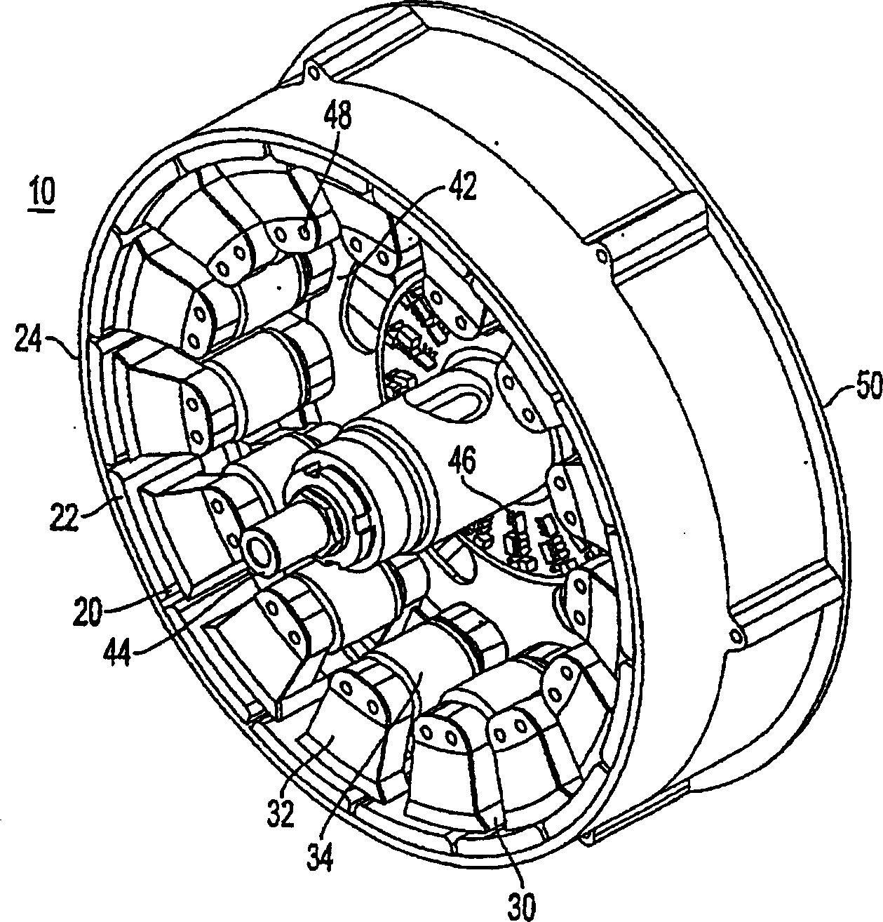
[0026] The motor of the present invention is suitable for driving the wheels of automobiles, motorcycles, bicycles or the like. The figures thus illustrate, by way of example, the construction of an electric machine which can be incorporated into a wheel and whose stator is rigidly arranged on a fixed shaft and surrounded by a rotor to drive the wheel. However, it should be noted that the vehicle in which the motor of the present invention is applied in the context is only an illustrative example of various specific applications.

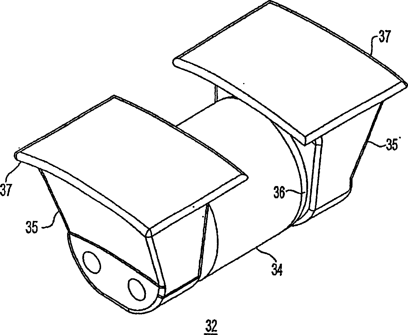
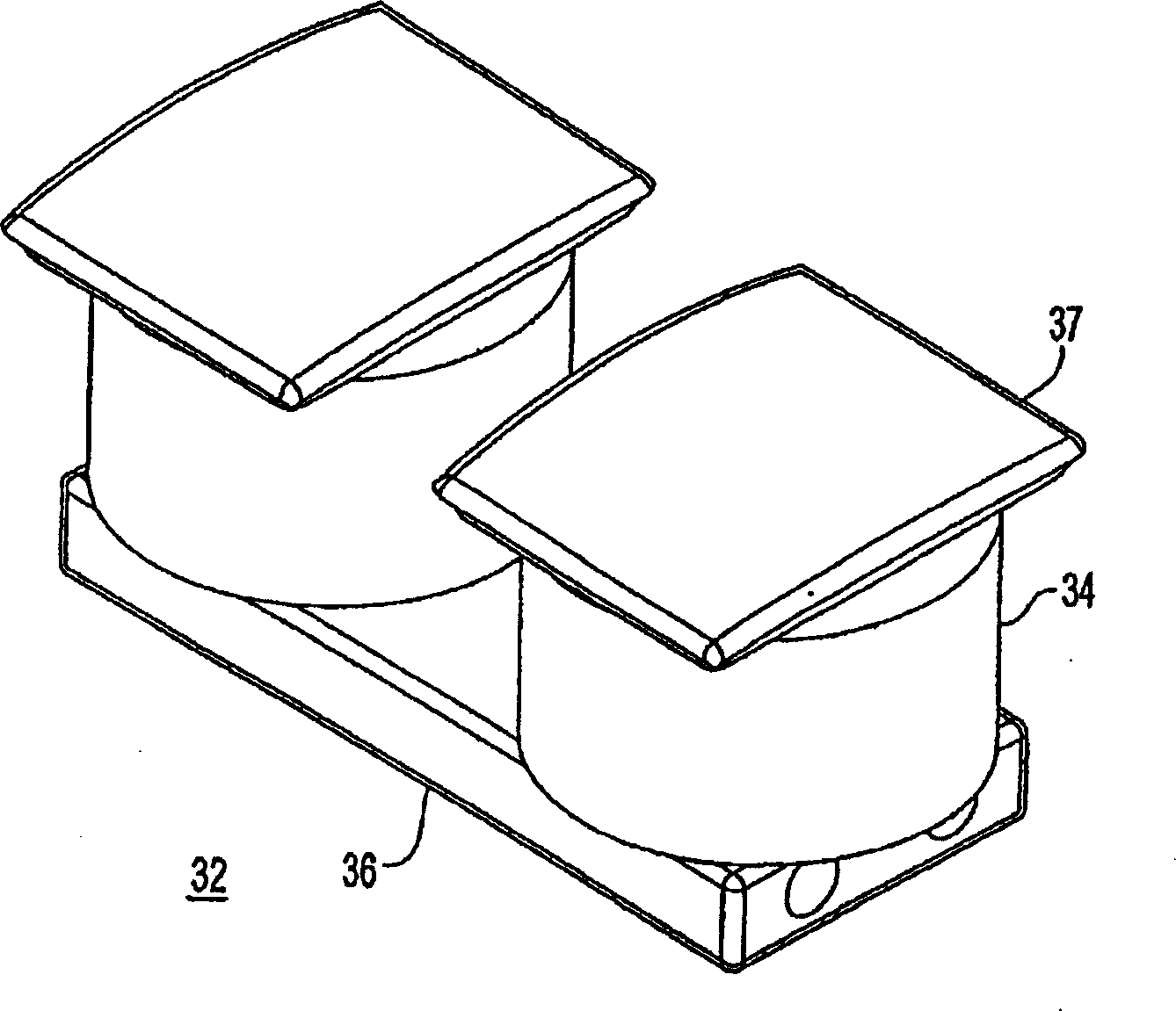
[0027] Such as figure 1 As shown in the cross-sectional view of , the motor 10 includes an annular permanent magnet rotor 20 and an annular stator structure 30 separated by a radial air gap. The stator includes a plurality of ferromagnetic insulating elements. Core segments 32, made of magnetically permeable material and spaced apart from each other without direct contact, have respective windings 34 thereon. The rotor includes a plurality of per...


PUM


Abstract

An electric generator comprising a rotor having a plurality of permanent magnet elements arranged on a circular ring structure around a rotating shaft, the magnetic polarity of the magnet elements is continuously alternating along the surface of the inner ring, and the rotor is connected to the rotor through a radial air gap Spaced stators. The stator includes a plurality of magnetic core segments having respective coils wound thereon to form stator windings, the core segments being spaced from one another without direct contact and disposed along a radial air gap. Each stator segment includes a plurality of poles aligned with each other in a direction parallel to the axis of rotation. The stator thus comprises a plurality of radially arranged stator pole groups which are arranged axially apart from each other.

Description

[0001] related application [0002] This application is a continuation of co-pending US Application Serial No. 09 / 966,101, filed October 1,2001. [0003] This application contains subject matter that is related to the following pending U.S. patent applications including: U.S. Application No. 10 / 440,118 filed May 19, 2003 by Maslov, U.S. Application No. 09 / 826,423 filed April 5, 2001 by Maslov et al. , Maslov et al., US Application Serial No. 09 / 826,422, filed April 5, 2001, which applications are commonly assigned herewith. The contents disclosed in these applications are incorporated in this application by reference in their entirety. technical field [0004] The present invention relates to rotating electric machines, and more particularly to electric machines having a plurality of rotor elements and stator elements comprising a plurality of poles arranged in a direction parallel to the axis of rotation. Background technique [0005] Gradual improvements in electronic sy...

Claims


Application Information

Patent Timeline
IPC IPC(8): H02K1/27F03D9/00H02K1/14H02K1/18H02K3/18H02K7/18H02K21/22
CPCH02K1/14H02K1/141H02K1/187H02K7/1823H02K7/183H02K21/22H02K21/227H02K2201/12F03D9/25Y02E10/72H02K1/2791H02K1/12H02K1/27
Inventor 鲍里斯·A·马斯洛夫
Owner WAVECREST LAB LLC
Why Eureka
Eureka Blog
Learn More