Eureka AIR delivers breakthrough ideas for toughest innovation challenges, trusted by R&D personnel around the world.

Rotary electric motor having axially aligned stator poles and/or rotor poles

A rotary, electric technology applied in the direction of synchronous motors, motors, motors, etc. with stationary armatures and rotating magnets, which can solve the problem of not fully realizing the benefits

Inactive Publication Date: 2005-01-05
WAVECREST LAB LLC
View PDF2 Cites 15 Cited by
  • Summary
  • Abstract
  • Description
  • Claims
  • Application Information

AI Technical Summary

Problems solved by technology

[0008] While significant advantages can be derived from the above efforts, it has been found that the benefits gained from using the three-dimensional aspects of motor structures have not been fully realized

Method used


Image

  • Rotary electric motor having axially aligned stator poles and/or rotor poles
  • Rotary electric motor having axially aligned stator poles and/or rotor poles
  • Rotary electric motor having axially aligned stator poles and/or rotor poles

Examples


Embodiment Construction

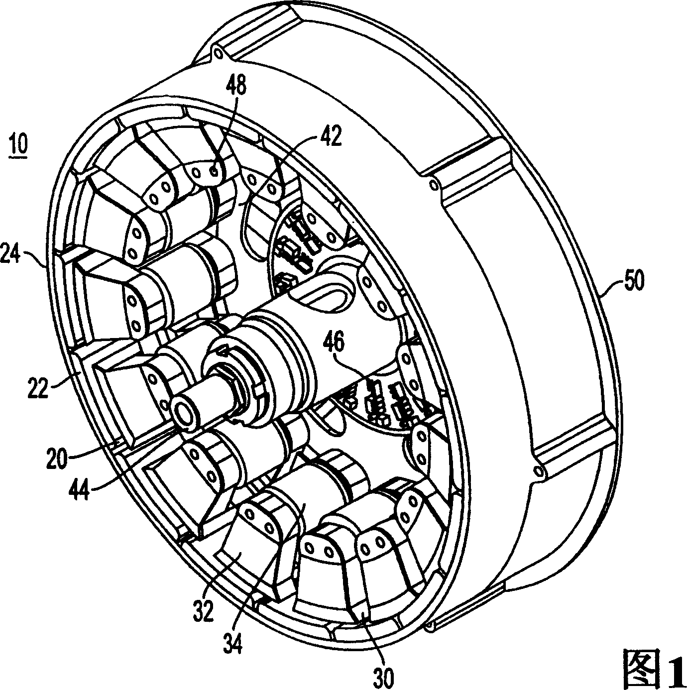
[0024] The motor of the present invention is suitable for use in driving wheels of automobiles, motorcycles, bicycles, and the like. Thus, the description of the drawings describes the structure of an electric machine that can be accommodated in a wheel, the stator being rigidly mounted on a fixed shaft and surrounded by a rotor for driving the wheel. It should be understood, however, that the vehicular situation is but one example of the many specific applications in which the electric machine of the present invention may be employed.

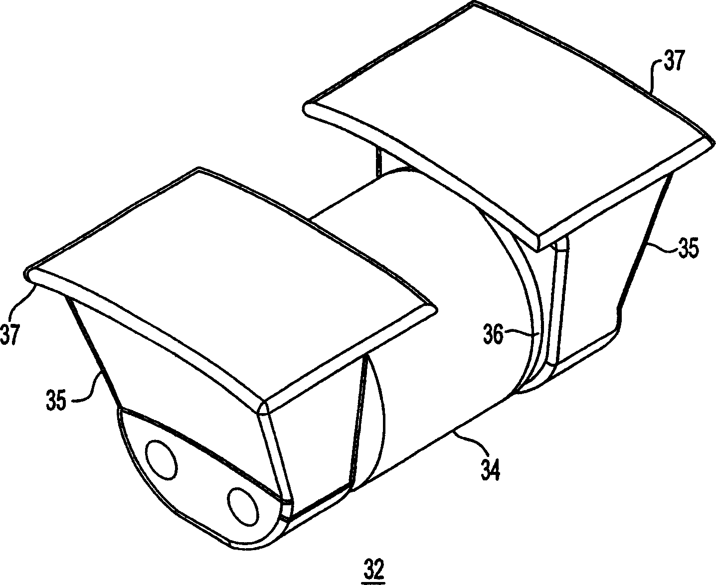
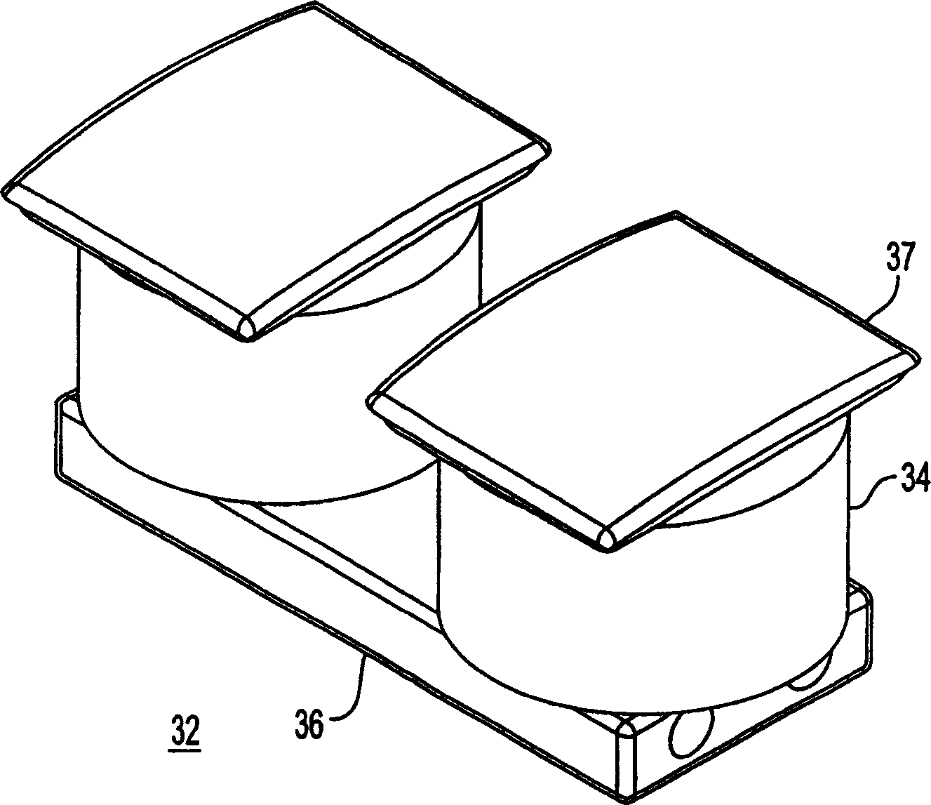
[0025] As shown in the cross-sectional view of FIG. 1 , the electric machine 10 includes an annular permanent magnet rotor 20 and an annular stator structure 30 separated by a radial air gap. The stator comprises a number of ferromagnetically isolated elements. Core segments 32 made of magnetically permeable material and isolated from each other from direct contact have respective windings 34 formed thereon. The rotor includes a plurality of...


PUM


Abstract

A rotary electric motor comprises a rotor having a plurality of permanent magnet elements disposed in an annular ring configuration about an axis of rotation, the magnet elements successively alternating in magnetic polarity along an inner annular surface, and a stator spaced from the rotor by a radial air gap. The stator includes a plurality of magnetic core segments having respective coils wound thereon to form stator windings, the core segments separated from direct contact with each other and disposed along the radial air gap. Each stator segment comprises a pair of poles aligned with each other in a direction parallel to the axis of rotation. Thus the stator comprises a first set of stator poles in radial alignment and an axially displaced second set of stator poles in radial alignment.

Description

[0001] related application [0002] This application contains references to co-pending U.S. Application Serial No. 09 / 826,423, filed April 5, 2001 by Maslov et al. and co-pending U.S. Application Serial No. 09 / 826,422, filed April 5, 2001 The subject matter of the US application, both of which are commonly assigned to the present application. The disclosures of both of these applications are hereby incorporated by reference. technical field [0003] The present invention relates to rotary electric machines, and more particularly to electric machines having a plurality of rotor elements and a stator element comprising a plurality of poles aligned in a direction parallel to the axis of rotation of the electric machine. Background technique [0004] Continuous improvements in electronic systems, such as those based on microcontrollers and microprocessors for motor control applications, and the availability of improved portable power sources have enabled the development of effi...

Claims


Application Information

Patent Timeline
Patent Type & Authority Applications(China)
IPC IPC(8): F03D9/00H02K1/14H02K1/18H02K1/27H02K3/18H02K7/18H02K21/22
CPCH02K7/1823H02K1/187F03D9/002Y02E10/725H02K1/141H02K7/183Y02T10/641H02K1/14H02K21/22H02K2201/12H02K1/2786F03D9/25Y02E10/72H02K1/2791H02K1/18
Inventor 博里斯·A·马斯洛夫扎雷·S·索格霍莫尼安
Owner WAVECREST LAB LLC
Why Eureka
Eureka Blog
Learn More