Insertion tool for ocular implant and method for using same

A technology for inserting tools and implants, applied in ophthalmic surgery, ophthalmic treatment, etc., which can solve problems such as wrong positioning, inability of inserting tools to position shunts correctly, and weakened visibility of hands

Inactive Publication Date: 2006-06-28
BECTON DICKINSON & CO
View PDF1 Cites 2 Cited by
  • Summary
  • Abstract
  • Description
  • Claims
  • Application Information

AI Technical Summary

Problems solved by technology

This typically results in a two-handed operation, as the surgeon must counteract the forces created by insertion by gripping the tip of the insertion tool
In addition, due to the use of two hands, visibility is further impaired, creating a risk of mispositioning, which results in incorrect positioning of the insertion tool and the shunt not entering the incision area

Method used


Image

  • Insertion tool for ocular implant and method for using same
  • Insertion tool for ocular implant and method for using same
  • Insertion tool for ocular implant and method for using same

Examples


Embodiment Construction

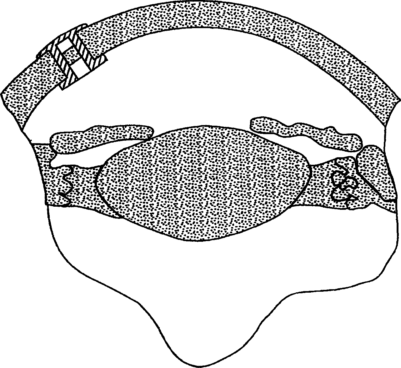
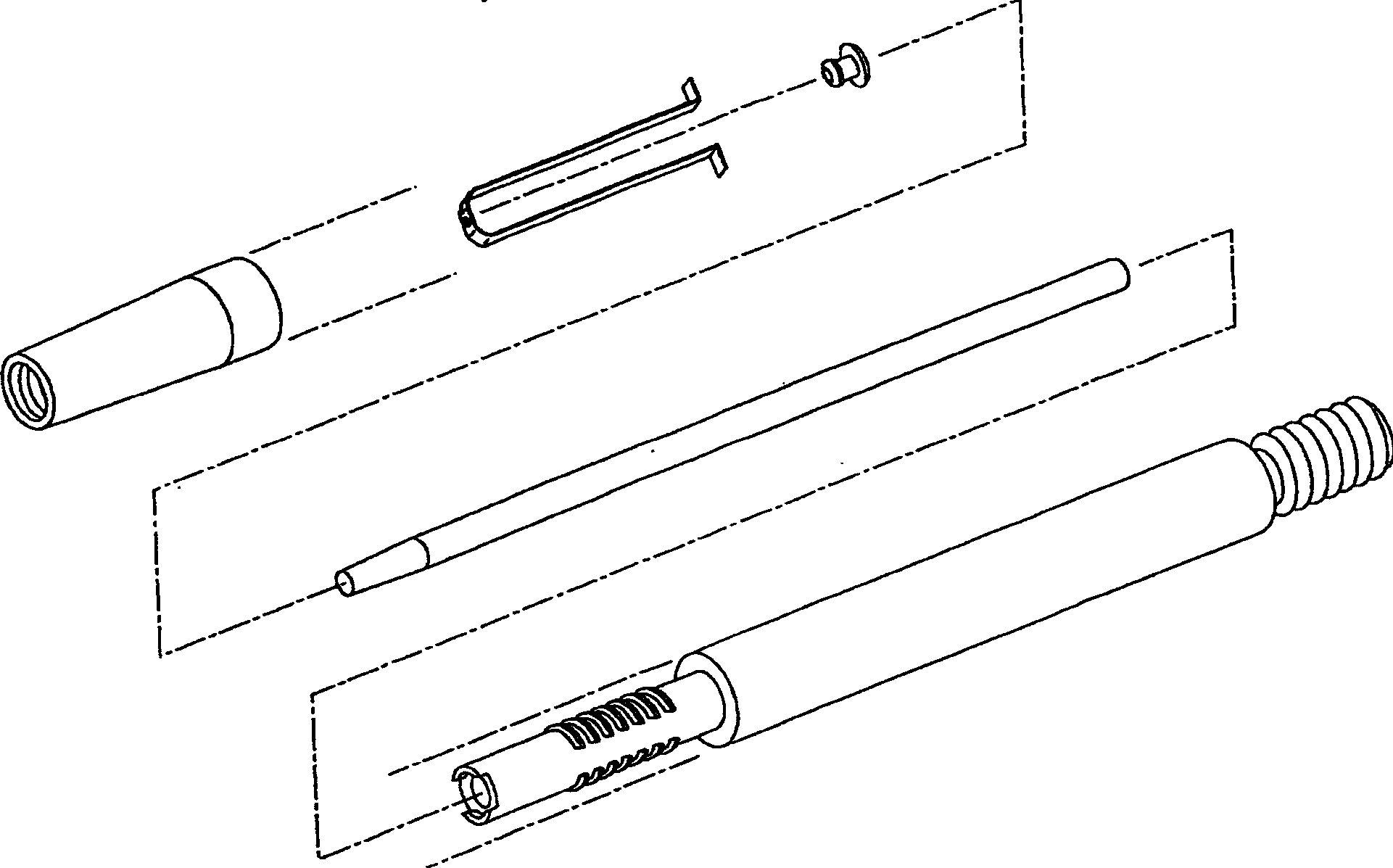
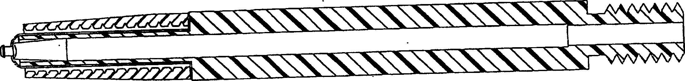
[0040] A shunt that penetrates the cornea (hereinafter referred to as a shunt) is used to reduce intraocular pressure (IOP) in the eye by draining aqueous humor from the inner chamber of the eyeball through the cornea to the terafilum. To do this, a shunt must be implanted in the cornea of ​​the eye through a small incision and run through the inner and outer surfaces of the cornea. However, shunts are very small and difficult to manipulate and handle during such insertions. To address this problem, embodiments of the present invention described below enable the surgeon to hold the shunt in place by gently manipulating the shunt at the distal end of the installation tool using a thin elastic material until manually released. The elastic material can include many polymeric materials such as polybutadiene, polyisobutylene and polyisoprene or natural rubber. Preferably, only a small portion of the shunt is secured during installation in each additional embodiment, so that the ma...


PUM


Abstract

An insertion tool consisting of an elastic band, ejector pin, and mandrel for securing a transcorneal shunt during an insertion procedure. The proximal flange of the shunt is lightly secured in place within the visible position within the adaptable opening of the elastic band at the distal end of the ejection pin. A sliding mechanism is provided to drive the cartridge assembly along the outer surface of the insertion tool while applying tension to the elastic band, enlarging the opening diameter to secure the shunt and gently release the shunt when required. A preferred embodiment of the insertion tool utilizes a detachable fiber bundle, a transparent detachable mylar sheet or septum sheet, a cantilevered fork, a collet assembly or a flexible jaw collet to gently secure and release the shunt during insertion.

Description

technical field [0001] The present invention relates to devices for use with ocular and non-ocular implants, and more particularly, to insertion tools and methods for controlled insertion of transcorneal shunts through the cornea of ​​the eye for use in reducing intraocular pressure . Embodiments of the present invention can be used in both transcorneal and transscleral instances. Background technique [0002] Glaucoma, caused by the degeneration of optic nerve cells, is the second leading cause of preventable blindness in the world today. The cardinal symptom of glaucoma is high intraocular pressure, or "IOP", caused primarily by the inability of the trabecular meshwork to drain adequate aqueous humor from the eye. The goal of glaucoma treatment is therefore to protect the optic nerve and preserve visual function by aiming at lowering the IOP in different ways, such as by medicine or surgery including surgical methods such as trabeculectomy and the use of implants. [00...

Claims


Application Information

Patent Timeline
Patent Type & Authority Applications(China)
IPC IPC(8): A61F9/00A61F9/007
CPCA61F9/007A61F9/00781A61F9/00
Inventor J·B·泰勒E·G·李M·B·马尔赫恩T·J·莫里尔D·M·科特
Owner BECTON DICKINSON & CO
Why Eureka
Try Eureka